How to Use Mosfetti 4 channel MOSFET switch: Examples, Pinouts, and Specs
Introduction
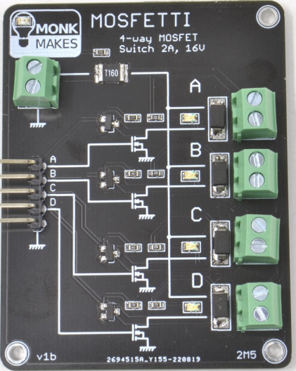
The Mosfetti 4 Channel MOSFET Switch (Manufacturer Part ID: SKU00099) by Monk Makes is a compact and efficient electronic switch designed for controlling high-current loads. Utilizing MOSFET technology, this module allows for precise and reliable switching with minimal heat generation. It features four independent channels, making it ideal for applications requiring multiple load control.
Explore Projects Built with Mosfetti 4 channel MOSFET switch


Explore Projects Built with Mosfetti 4 channel MOSFET switch
Common Applications and Use Cases
- Driving high-current LEDs or LED strips
- Controlling DC motors or solenoids
- Switching power to resistive loads such as heaters
- General-purpose high-current switching in automation projects
- Integration with microcontrollers like Arduino, Raspberry Pi, or ESP32
Technical Specifications
Key Technical Details
- Input Voltage (Logic): 3.3V to 5V (compatible with most microcontrollers)
- Load Voltage (Drain-Source): Up to 30V DC
- Maximum Load Current (per channel): 5A (continuous)
- MOSFET Type: N-channel
- On-Resistance (RDS(on)): < 0.1Ω
- Board Dimensions: 50mm x 25mm
- Connector Type: Screw terminals for load connections, pin headers for logic inputs
- Protection Features: Flyback diode for inductive loads
Pin Configuration and Descriptions
The Mosfetti module has two main interfaces: the Logic Input Pins and the Load Output Terminals.
Logic Input Pins
| Pin Name | Description | Voltage Level |
|---|---|---|
| IN1 | Logic input for Channel 1 | 3.3V to 5V |
| IN2 | Logic input for Channel 2 | 3.3V to 5V |
| IN3 | Logic input for Channel 3 | 3.3V to 5V |
| IN4 | Logic input for Channel 4 | 3.3V to 5V |
| GND | Ground connection for logic signals | 0V |
Load Output Terminals
| Terminal Name | Description |
|---|---|
| OUT1 | Load output for Channel 1 |
| OUT2 | Load output for Channel 2 |
| OUT3 | Load output for Channel 3 |
| OUT4 | Load output for Channel 4 |
| GND | Common ground for load connections |
| VIN | Positive voltage supply for loads |
Usage Instructions
How to Use the Component in a Circuit
- Connect the Load:
- Attach the positive terminal of your load to the VIN terminal.
- Connect the negative terminal of your load to one of the OUTx terminals (e.g., OUT1 for Channel 1).
- Connect the Logic Inputs:
- Use the INx pins to control the corresponding channels. For example, applying a HIGH signal (3.3V or 5V) to IN1 will activate Channel 1.
- Connect the GND pin of the Mosfetti module to the ground of your microcontroller or logic source.
- Power the Module:
- Ensure the VIN terminal is supplied with the appropriate voltage for your load (up to 30V DC).
- Control the Channels:
- Use your microcontroller or logic circuit to send HIGH or LOW signals to the INx pins to switch the corresponding channels ON or OFF.
Important Considerations and Best Practices
- Heat Dissipation: While the MOSFETs are efficient, ensure adequate ventilation if operating near the maximum current rating.
- Inductive Loads: The module includes flyback diodes for protection, but ensure your load does not exceed the module's voltage and current ratings.
- Logic Level Compatibility: Verify that your microcontroller's logic voltage (3.3V or 5V) matches the input requirements of the Mosfetti module.
- Power Supply: Use a stable power supply for the load to avoid voltage fluctuations that could affect performance.
Example: Using Mosfetti with Arduino UNO
Below is an example of controlling a DC motor connected to Channel 1 using an Arduino UNO.
// Define the Mosfetti input pin connected to Arduino
const int mosfettiPin = 3; // IN1 connected to Arduino pin 3

void setup() {
  pinMode(mosfettiPin, OUTPUT); // Set the Mosfetti pin as an output
}

void loop() {
  digitalWrite(mosfettiPin, HIGH); // Turn on the load (e.g., motor)
  delay(2000); // Keep the load on for 2 seconds

  digitalWrite(mosfettiPin, LOW); // Turn off the load
  delay(2000); // Keep the load off for 2 seconds
}
Troubleshooting and FAQs
Common Issues and Solutions
The load does not turn on:
- Ensure the VIN terminal is connected to a power supply with the correct voltage for your load.
- Verify that the logic input pin (e.g., IN1) is receiving a HIGH signal (3.3V or 5V).
- Check all connections for loose wires or poor contact.
The module overheats:
- Confirm that the load current does not exceed 5A per channel.
- Ensure proper ventilation around the module to dissipate heat.
Inductive load causes noise or malfunction:
- The module includes flyback diodes, but if issues persist, consider adding external diodes or snubber circuits for additional protection.
Microcontroller resets when switching loads:
- This may be caused by voltage spikes or insufficient power supply decoupling. Add a capacitor (e.g., 100µF) across the power supply terminals.
FAQs
Q: Can I use the Mosfetti module with a 12V LED strip?
A: Yes, the Mosfetti module supports load voltages up to 30V DC. Ensure the total current of the LED strip does not exceed 5A per channel.
Q: Is the module compatible with 3.3V logic microcontrollers like ESP32?
A: Yes, the Mosfetti module accepts logic input voltages from 3.3V to 5V, making it compatible with most microcontrollers.
Q: Can I control all four channels simultaneously?
A: Yes, you can control all four channels independently or simultaneously, as long as the total current does not exceed the power supply's capacity.
Q: Does the module support AC loads?
A: No, the Mosfetti module is designed for DC loads only. Do not use it with AC loads.