Cirkit Designer Logo
Cirkit Designer
Your all-in-one circuit design IDE
Home / 
Component Documentation

How to Use 12v to 5v 3a USB C Buck Converter: Examples, Pinouts, and Specs

Image of 12v to 5v 3a USB C Buck Converter
Cirkit Designer LogoDesign with 12v to 5v 3a USB C Buck Converter in Cirkit Designer

Introduction

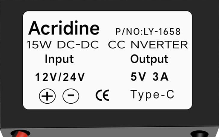
The 12V to 5V 3A USB C Buck Converter is a DC-DC step-down voltage regulator designed to convert a 12V input voltage to a stable 5V output voltage. It is capable of delivering up to 3A of current, making it ideal for powering USB devices such as smartphones, tablets, single-board computers (e.g., Raspberry Pi), and other 5V-powered electronics. This compact and efficient converter is commonly used in automotive, DIY electronics, and embedded systems projects.

Explore Projects Built with 12v to 5v 3a USB C Buck Converter

Use Cirkit Designer to design, explore, and prototype these projects online. Some projects support real-time simulation. Click "Open Project" to start designing instantly!
USB Power Supply with Overcurrent Protection
Image of USB Charging port: A project utilizing 12v to 5v 3a USB C Buck Converter in a practical application
This circuit is designed to step down voltage from a 12V battery to a lower voltage suitable for USB devices. It includes a buck converter connected to the battery through a fuse and fuse holder for overcurrent protection. The output of the buck converter is connected to a USB female port, providing a regulated power supply for USB-powered devices.
Cirkit Designer LogoOpen Project in Cirkit Designer
Battery-Powered Boost Converter with USB Type-C and BMS
Image of Weird Case: A project utilizing 12v to 5v 3a USB C Buck Converter in a practical application
This circuit is a power management and conversion system that includes a boost converter, battery management system (BMS), and various MOSFETs and passive components. It is designed to regulate and boost the voltage from a 2000mAh battery, providing stable power output through a USB Type C interface. The circuit also includes protection and switching mechanisms to ensure safe and efficient power delivery.
Cirkit Designer LogoOpen Project in Cirkit Designer
Battery-Powered ESP32 Devkit V1 with Buck Converter and Switch Control
Image of Autonomus Car: A project utilizing 12v to 5v 3a USB C Buck Converter in a practical application
This circuit is a power management system that uses two 18650 Li-ion batteries to supply power through a toggle switch and a rocker switch to an LM2956 Buck Converter. The buck converter steps down the voltage to a suitable level for a connected device via a Micro USB cable.
Cirkit Designer LogoOpen Project in Cirkit Designer
Battery-Powered 18650 Li-ion Charger with USB Output and Adjustable Voltage Regulator
Image of Breadboard: A project utilizing 12v to 5v 3a USB C Buck Converter in a practical application
This circuit is a battery management and power supply system that uses three 3.7V batteries connected to a 3S 10A Li-ion 18650 Charger Protection Board Module for balanced charging and protection. The system includes a TP4056 Battery Charging Protection Module for additional charging safety, a Step Up Boost Power Converter to regulate and boost the voltage, and a USB regulator to provide a stable 5V output, controlled by a push switch.
Cirkit Designer LogoOpen Project in Cirkit Designer

Explore Projects Built with 12v to 5v 3a USB C Buck Converter

Use Cirkit Designer to design, explore, and prototype these projects online. Some projects support real-time simulation. Click "Open Project" to start designing instantly!
Image of USB Charging port: A project utilizing 12v to 5v 3a USB C Buck Converter in a practical application
USB Power Supply with Overcurrent Protection
This circuit is designed to step down voltage from a 12V battery to a lower voltage suitable for USB devices. It includes a buck converter connected to the battery through a fuse and fuse holder for overcurrent protection. The output of the buck converter is connected to a USB female port, providing a regulated power supply for USB-powered devices.
Cirkit Designer LogoOpen Project in Cirkit Designer
Image of Weird Case: A project utilizing 12v to 5v 3a USB C Buck Converter in a practical application
Battery-Powered Boost Converter with USB Type-C and BMS
This circuit is a power management and conversion system that includes a boost converter, battery management system (BMS), and various MOSFETs and passive components. It is designed to regulate and boost the voltage from a 2000mAh battery, providing stable power output through a USB Type C interface. The circuit also includes protection and switching mechanisms to ensure safe and efficient power delivery.
Cirkit Designer LogoOpen Project in Cirkit Designer
Image of Autonomus Car: A project utilizing 12v to 5v 3a USB C Buck Converter in a practical application
Battery-Powered ESP32 Devkit V1 with Buck Converter and Switch Control
This circuit is a power management system that uses two 18650 Li-ion batteries to supply power through a toggle switch and a rocker switch to an LM2956 Buck Converter. The buck converter steps down the voltage to a suitable level for a connected device via a Micro USB cable.
Cirkit Designer LogoOpen Project in Cirkit Designer
Image of Breadboard: A project utilizing 12v to 5v 3a USB C Buck Converter in a practical application
Battery-Powered 18650 Li-ion Charger with USB Output and Adjustable Voltage Regulator
This circuit is a battery management and power supply system that uses three 3.7V batteries connected to a 3S 10A Li-ion 18650 Charger Protection Board Module for balanced charging and protection. The system includes a TP4056 Battery Charging Protection Module for additional charging safety, a Step Up Boost Power Converter to regulate and boost the voltage, and a USB regulator to provide a stable 5V output, controlled by a push switch.
Cirkit Designer LogoOpen Project in Cirkit Designer

Common Applications

  • Powering USB devices from a 12V car battery or power supply
  • Supplying 5V to microcontrollers, single-board computers, or IoT devices
  • Charging USB-C devices in automotive or off-grid setups
  • DIY electronics projects requiring a stable 5V power source

Technical Specifications

Below are the key technical details of the 12V to 5V 3A USB C Buck Converter:

Parameter Value
Input Voltage Range 8V to 24V
Output Voltage 5V ± 0.1V
Maximum Output Current 3A
Efficiency Up to 96%
Output Connector USB-C
Dimensions Varies by model (e.g., 25mm x 15mm)
Operating Temperature -40°C to +85°C

Pin Configuration and Descriptions

The converter typically has the following input and output connections:

Pin/Connector Description
VIN+ Positive input voltage terminal (8V to 24V)
VIN- Negative input voltage terminal (ground)
USB-C Port 5V output for powering USB devices

Usage Instructions

How to Use the Component in a Circuit

  1. Connect the Input Voltage:

    • Connect the VIN+ terminal to a 12V DC power source (e.g., car battery, adapter).
    • Connect the VIN- terminal to the ground of the power source.
  2. Connect the Output:

    • Plug your USB device into the USB-C port of the converter.
    • Ensure the connected device does not exceed the 3A current limit.
  3. Verify Connections:

    • Double-check all connections to avoid reverse polarity or short circuits.
    • Use a multimeter to confirm the input and output voltages if necessary.
  4. Power On:

    • Turn on the 12V power source. The converter will step down the voltage to 5V and supply power to the connected USB device.

Important Considerations and Best Practices

  • Input Voltage Range: Ensure the input voltage is within the specified range (8V to 24V). Exceeding this range may damage the converter.
  • Heat Dissipation: At high currents (e.g., 3A), the converter may generate heat. Use proper ventilation or a heatsink if necessary.
  • Load Current: Do not exceed the 3A output current limit to prevent overheating or damage.
  • Polarity Protection: Verify the polarity of the input connections to avoid damaging the converter.

Example: Using with an Arduino UNO

The 12V to 5V 3A USB C Buck Converter can be used to power an Arduino UNO via its USB port. Below is an example of how to connect and use it:

  1. Connect the VIN+ and VIN- terminals of the converter to a 12V DC power source.
  2. Plug the USB-C cable from the converter into the Arduino UNO's USB port.
  3. The Arduino UNO will receive a stable 5V power supply from the converter.

Here is a simple Arduino sketch to test the setup by blinking an LED:

// Blink an LED connected to pin 13 on the Arduino UNO
// Ensure the Arduino is powered via the 12V to 5V Buck Converter

void setup() {
  pinMode(13, OUTPUT); // Set pin 13 as an output
}

void loop() {
  digitalWrite(13, HIGH); // Turn the LED on
  delay(1000);            // Wait for 1 second
  digitalWrite(13, LOW);  // Turn the LED off
  delay(1000);            // Wait for 1 second
}

Troubleshooting and FAQs

Common Issues and Solutions

  1. No Output Voltage:

    • Cause: Incorrect input connections or insufficient input voltage.
    • Solution: Verify the polarity and ensure the input voltage is within the 8V to 24V range.
  2. Overheating:

    • Cause: Excessive load current or poor ventilation.
    • Solution: Reduce the load current or improve heat dissipation with a heatsink or fan.
  3. Device Not Charging:

    • Cause: USB device requires more than 3A or incompatible USB-C cable.
    • Solution: Ensure the device's current requirement is ≤3A and use a high-quality USB-C cable.
  4. Voltage Drop Under Load:

    • Cause: Input voltage is too low or wiring resistance is too high.
    • Solution: Use a stable 12V power source and minimize wire length/resistance.

FAQs

Q: Can I use this converter with a 24V input?
A: Yes, the converter supports input voltages up to 24V. However, ensure the input voltage does not exceed this limit.

Q: Is the USB-C port compatible with fast charging?
A: This converter provides a fixed 5V output and does not support fast charging protocols like Quick Charge or Power Delivery.

Q: Can I use this converter to power a Raspberry Pi?
A: Yes, the converter can power a Raspberry Pi as long as the total current draw (including peripherals) does not exceed 3A.

Q: Does the converter have reverse polarity protection?
A: Most models do not include reverse polarity protection. Always verify the input connections before powering on.