
How to Use 32mm 8x8 dot matrix column cathode LED display: Examples, Pinouts, and Specs
 Design with 32mm 8x8 dot matrix column cathode LED display in Cirkit Designer
Introduction
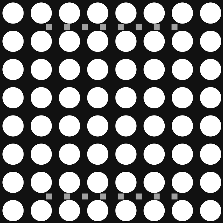
The 32mm 8x8 dot matrix column cathode LED display is a compact and versatile component designed for visual output. It consists of an 8x8 grid of light-emitting diodes (LEDs) arranged in a column cathode configuration. This design simplifies the control of individual LEDs, making it ideal for displaying alphanumeric characters, symbols, and simple graphics.
Explore Projects Built with 32mm 8x8 dot matrix column cathode LED display
 Open Project in Cirkit Designer
 Open Project in Cirkit Designer
 Open Project in Cirkit Designer
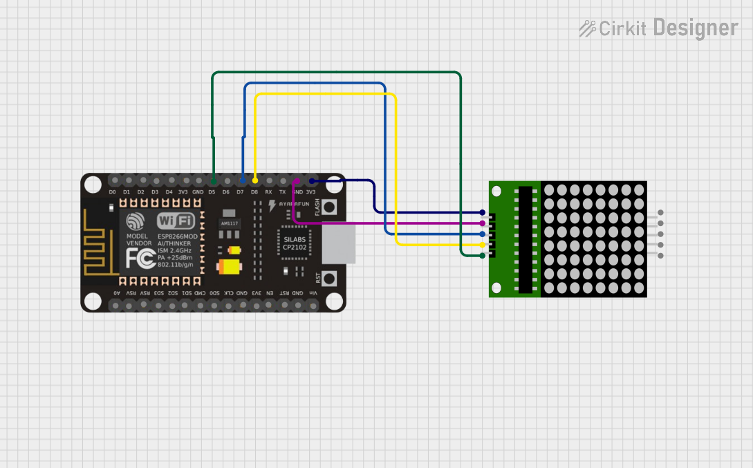 Open Project in Cirkit Designer
Explore Projects Built with 32mm 8x8 dot matrix column cathode LED display
Open Project in Cirkit DesignerOpen Project in Cirkit DesignerOpen Project in Cirkit DesignerOpen Project in Cirkit DesignerCommon Applications and Use Cases
- Digital clocks and timers
- Scrolling text displays
- Simple animations and graphics
- Status indicators in embedded systems
- Educational projects and prototyping
Technical Specifications
Below are the key technical details of the 32mm 8x8 dot matrix column cathode LED display:
| Parameter | Value |
|---|---|
| Dimensions | 32mm x 32mm |
| LED Configuration | 8x8 grid (64 LEDs total) |
| LED Type | Red (common, may vary) |
| Operating Voltage | 2.0V - 2.2V per LED |
| Forward Current | 20mA per LED (max) |
| Reverse Voltage | 5V (max) |
| Cathode Configuration | Column cathode |
| Operating Temperature | -40°C to +85°C |
Pin Configuration and Descriptions
The 32mm 8x8 dot matrix display has 16 pins, with 8 pins corresponding to the rows (anodes) and 8 pins corresponding to the columns (cathodes). Below is the pinout:
| Pin Number | Description | Function |
|---|---|---|
| 1-8 | Row Anodes (R1-R8) | Positive terminals for rows |
| 9-16 | Column Cathodes (C1-C8) | Negative terminals for columns |
Note: The exact pin numbering and layout may vary depending on the manufacturer. Always refer to the datasheet for your specific model.
Usage Instructions
How to Use the Component in a Circuit
- Power Requirements: Ensure that the forward voltage and current for each LED are within the specified range (2.0V-2.2V, 20mA max). Use current-limiting resistors to prevent damage to the LEDs.
- Matrix Control: To control the display, you need to activate specific rows and columns. For example:
- Set a row (anode) to HIGH.
- Set a column (cathode) to LOW to light up the corresponding LED.
- Multiplexing: Since controlling all 64 LEDs simultaneously is impractical, use multiplexing techniques to light up one row or column at a time in rapid succession. This creates the illusion of a fully lit display.
Important Considerations and Best Practices
- Current Limiting: Always use resistors to limit the current through each LED. A typical value is 220Ω to 330Ω.
- Driver ICs: For ease of control, consider using driver ICs like the MAX7219 or 74HC595 shift registers.
- Refresh Rate: Maintain a refresh rate of at least 60Hz to avoid flickering.
- Heat Management: Ensure proper ventilation if the display is used for extended periods.
Example: Connecting to an Arduino UNO
Below is an example of how to control the 32mm 8x8 dot matrix display using an Arduino UNO and a MAX7219 driver IC.
Circuit Diagram
- Connect the 8x8 dot matrix display to the MAX7219 as per the datasheet.
- Connect the MAX7219 to the Arduino UNO:
- DIN → Pin 11
- CS → Pin 10
- CLK → Pin 13
- VCC → 5V
- GND → GND
Arduino Code
#include <LedControl.h>
// Include the LedControl library for MAX7219 control

// Initialize the LedControl object
// Parameters: DIN pin, CLK pin, CS pin, number of devices
LedControl lc = LedControl(11, 13, 10, 1);

void setup() {
  lc.shutdown(0, false); // Wake up the MAX7219
  lc.setIntensity(0, 8); // Set brightness (0-15)
  lc.clearDisplay(0);    // Clear the display
}

void loop() {
  // Example: Display a smiley face pattern
  byte smiley[8] = {
    B00111100, // Row 1
    B01000010, // Row 2
    B10100101, // Row 3
    B10000001, // Row 4
    B10100101, // Row 5
    B10011001, // Row 6
    B01000010, // Row 7
    B00111100  // Row 8
  };

  for (int row = 0; row < 8; row++) {
    lc.setRow(0, row, smiley[row]);
    // Set each row of the display
  }
  delay(1000); // Hold the pattern for 1 second
}
Note: The
LedControllibrary can be installed via the Arduino Library Manager.
Troubleshooting and FAQs
Common Issues
LEDs Not Lighting Up
- Cause: Incorrect wiring or insufficient power supply.
- Solution: Double-check the connections and ensure the power supply meets the voltage and current requirements.
Flickering Display
- Cause: Low refresh rate or poor multiplexing.
- Solution: Increase the refresh rate or use a driver IC like MAX7219 for smoother control.
Dim LEDs
- Cause: High resistance in current-limiting resistors.
- Solution: Use lower-value resistors (e.g., 220Ω) to increase brightness.
Overheating
- Cause: Excessive current through LEDs.
- Solution: Ensure proper current limiting and avoid exceeding the maximum ratings.
FAQs
Q: Can I use this display with a Raspberry Pi?
A: Yes, you can use this display with a Raspberry Pi. Use GPIO pins and a driver IC like MAX7219 for easier control.
Q: Can I display custom patterns?
A: Absolutely! You can define custom patterns as 8-byte arrays and send them to the display using your microcontroller.
Q: What is the lifespan of the LEDs?
A: The LEDs typically have a lifespan of 50,000 hours under normal operating conditions.
Q: Can I chain multiple displays together?
A: Yes, with a driver IC like MAX7219, you can daisy-chain multiple displays for larger output.
This concludes the documentation for the 32mm 8x8 dot matrix column cathode LED display.