Cirkit Designer Logo
Cirkit Designer
Your all-in-one circuit design IDE
Home / 
Component Documentation

How to Use usb module 5v: Examples, Pinouts, and Specs

Image of usb module 5v
Cirkit Designer LogoDesign with usb module 5v in Cirkit Designer

Introduction

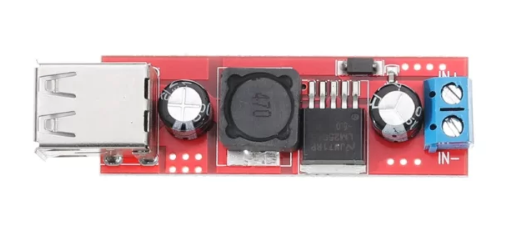
The USB Module 5V is a versatile and essential component for powering various electronic projects and devices. It converts the standard 5V output from a USB port into a stable power supply, making it ideal for use in prototyping, DIY projects, and embedded systems. This module is particularly useful for powering microcontrollers, sensors, and other low-power devices.

Explore Projects Built with usb module 5v

Use Cirkit Designer to design, explore, and prototype these projects online. Some projects support real-time simulation. Click "Open Project" to start designing instantly!
DC-DC Converter and Relay Module Power Distribution System
Image of relay: A project utilizing usb module 5v in a practical application
This circuit consists of a DC-DC converter powering a 6-channel power module, which in turn supplies 5V to a 2-relay module. The power module distributes the converted voltage to the relay module, enabling it to control external devices.
Cirkit Designer LogoOpen Project in Cirkit Designer
Battery-Powered Lora G2 Node Station with 18650 Li-ion Batteries and Boost Converter
Image of Custom-Lora-G2-Node: A project utilizing usb module 5v in a practical application
This circuit is a portable power supply system that uses multiple 18650 Li-ion batteries to provide a stable 5V output through a boost converter. It includes a fast charging module with a USB-C input for recharging the batteries and a battery indicator for monitoring the battery status. The system powers a Lora G2 Node Station, making it suitable for wireless communication applications.
Cirkit Designer LogoOpen Project in Cirkit Designer
Dual Hub Motor Control System with USB to TTL Interface and Relay Switching
Image of Hub Motor & servo motor Connection: A project utilizing usb module 5v in a practical application
This circuit is designed to control two hub motors using a HUB driver, powered by a DC-DC converter and a power module. The USB to TTL converter allows for communication with the HUB driver, and a 5V relay module is used to switch the motors on and off.
Cirkit Designer LogoOpen Project in Cirkit Designer
Battery-Powered USB Charger with LED Indicator and DC Motor
Image of Copy of Hand Crank mobile charger : A project utilizing usb module 5v in a practical application
This circuit converts AC power to DC using a bridge rectifier and regulates the voltage to 5V with a 7805 voltage regulator. It powers a USB port and indicates power status with an LED, while also providing a charging interface through a multi-charging cable.
Cirkit Designer LogoOpen Project in Cirkit Designer

Explore Projects Built with usb module 5v

Use Cirkit Designer to design, explore, and prototype these projects online. Some projects support real-time simulation. Click "Open Project" to start designing instantly!
Image of relay: A project utilizing usb module 5v in a practical application
DC-DC Converter and Relay Module Power Distribution System
This circuit consists of a DC-DC converter powering a 6-channel power module, which in turn supplies 5V to a 2-relay module. The power module distributes the converted voltage to the relay module, enabling it to control external devices.
Cirkit Designer LogoOpen Project in Cirkit Designer
Image of Custom-Lora-G2-Node: A project utilizing usb module 5v in a practical application
Battery-Powered Lora G2 Node Station with 18650 Li-ion Batteries and Boost Converter
This circuit is a portable power supply system that uses multiple 18650 Li-ion batteries to provide a stable 5V output through a boost converter. It includes a fast charging module with a USB-C input for recharging the batteries and a battery indicator for monitoring the battery status. The system powers a Lora G2 Node Station, making it suitable for wireless communication applications.
Cirkit Designer LogoOpen Project in Cirkit Designer
Image of Hub Motor & servo motor Connection: A project utilizing usb module 5v in a practical application
Dual Hub Motor Control System with USB to TTL Interface and Relay Switching
This circuit is designed to control two hub motors using a HUB driver, powered by a DC-DC converter and a power module. The USB to TTL converter allows for communication with the HUB driver, and a 5V relay module is used to switch the motors on and off.
Cirkit Designer LogoOpen Project in Cirkit Designer
Image of Copy of Hand Crank mobile charger : A project utilizing usb module 5v in a practical application
Battery-Powered USB Charger with LED Indicator and DC Motor
This circuit converts AC power to DC using a bridge rectifier and regulates the voltage to 5V with a 7805 voltage regulator. It powers a USB port and indicates power status with an LED, while also providing a charging interface through a multi-charging cable.
Cirkit Designer LogoOpen Project in Cirkit Designer

Common Applications and Use Cases

  • Microcontroller Power Supply: Provides a stable 5V power source for microcontrollers like Arduino, ESP8266, and Raspberry Pi.
  • Sensor Power Supply: Powers various sensors and modules in electronic projects.
  • Portable Projects: Ideal for portable projects where a USB power bank can be used as a power source.
  • Prototyping: Useful in breadboard and prototyping setups to provide a reliable power supply.

Technical Specifications

Key Technical Details

Parameter Value
Input Voltage 4.75V - 5.25V (USB)
Output Voltage 5V
Output Current Up to 1A
Efficiency Up to 90%
Operating Temperature -40°C to 85°C
Dimensions 25mm x 15mm x 10mm

Pin Configuration and Descriptions

Pin Number Pin Name Description
1 VCC 5V Output
2 GND Ground
3 D+ USB Data Positive (not used for power)
4 D- USB Data Negative (not used for power)
5 ID USB ID (not used for power)

Usage Instructions

How to Use the Component in a Circuit

  1. Connect the USB Module:

    • Plug the USB module into a USB port or connect it to a USB power source.
  2. Powering a Microcontroller:

    • Connect the VCC pin of the USB module to the 5V input pin of the microcontroller.
    • Connect the GND pin of the USB module to the ground (GND) pin of the microcontroller.
  3. Powering Sensors and Modules:

    • Connect the VCC pin of the USB module to the power input pin of the sensor or module.
    • Connect the GND pin of the USB module to the ground (GND) pin of the sensor or module.

Important Considerations and Best Practices

  • Current Limitation: Ensure that the total current draw of the connected devices does not exceed the maximum output current of the USB module (1A).
  • Heat Dissipation: If the module gets warm during operation, ensure proper ventilation to avoid overheating.
  • Stable Connections: Use reliable connectors and cables to prevent intermittent power issues.

Troubleshooting and FAQs

Common Issues Users Might Face

  1. No Power Output:

    • Solution: Check the USB connection and ensure the power source is providing 5V. Verify that the VCC and GND connections are secure.
  2. Overheating:

    • Solution: Ensure that the total current draw does not exceed 1A. Provide adequate ventilation or cooling if necessary.
  3. Intermittent Power:

    • Solution: Check for loose connections or faulty cables. Use high-quality connectors and cables to ensure stable power delivery.

FAQs

Q1: Can I use this module to power an Arduino UNO?

  • A1: Yes, you can use the USB module to power an Arduino UNO by connecting the VCC pin to the 5V pin and the GND pin to the GND pin of the Arduino.

Q2: What is the maximum current output of this module?

  • A2: The maximum current output of the USB module is 1A.

Q3: Can I use this module with a USB power bank?

  • A3: Yes, you can use a USB power bank as a power source for the USB module.

Example Code for Arduino UNO

Here is an example of how to use the USB module to power an Arduino UNO and blink an LED:

// Example code to blink an LED using Arduino UNO powered by USB Module 5V

const int ledPin = 13; // Pin number for the built-in LED

void setup() {
  pinMode(ledPin, OUTPUT); // Set the LED pin as an output
}

void loop() {
  digitalWrite(ledPin, HIGH); // Turn the LED on
  delay(1000); // Wait for 1 second
  digitalWrite(ledPin, LOW); // Turn the LED off
  delay(1000); // Wait for 1 second
}

This code will blink the built-in LED on the Arduino UNO at 1-second intervals. Ensure that the USB module is properly connected to the Arduino UNO as described in the usage instructions.


This documentation provides a comprehensive guide to using the USB Module 5V, covering its technical specifications, usage instructions, and troubleshooting tips. Whether you are a beginner or an experienced user, this guide will help you effectively utilize the USB module in your electronic projects.