
How to Use Screw terminal - 2 pins: Examples, Pinouts, and Specs
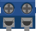
 Design with Screw terminal - 2 pins in Cirkit Designer
Introduction
A screw terminal with two pins is a simple yet versatile component used for creating secure and reliable electrical connections. It allows wires to be easily attached or detached by tightening or loosening screws, making it ideal for applications where frequent reconfiguration or maintenance is required. This component is commonly used in prototyping, industrial control systems, power distribution, and DIY electronics projects.
Explore Projects Built with Screw terminal - 2 pins
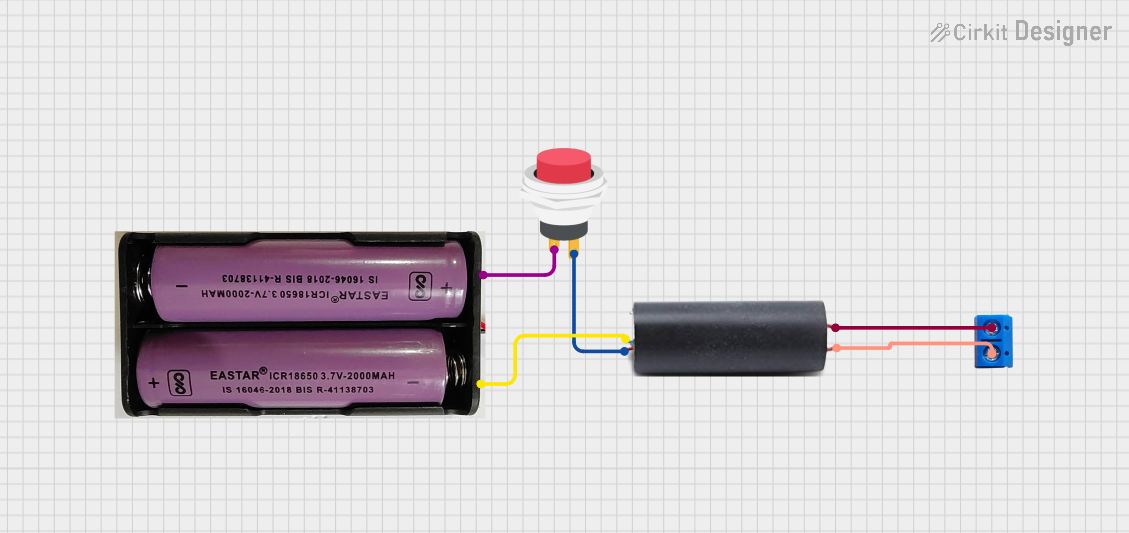 Open Project in Cirkit Designer
 Open Project in Cirkit Designer
 Open Project in Cirkit Designer
 Open Project in Cirkit Designer
Explore Projects Built with Screw terminal - 2 pins
Open Project in Cirkit DesignerOpen Project in Cirkit DesignerOpen Project in Cirkit DesignerOpen Project in Cirkit DesignerCommon Applications and Use Cases
- Connecting wires in prototyping and breadboard setups
- Power distribution in low-voltage circuits
- Industrial control systems and automation
- DIY electronics and hobbyist projects
- Secure connections for sensors, motors, and other peripherals
Technical Specifications
Key Technical Details
- Number of Pins: 2
- Rated Voltage: Typically up to 300V (varies by model)
- Rated Current: Typically up to 10A (varies by model)
- Wire Gauge Compatibility: 16-26 AWG (varies by model)
- Material: Plastic housing with metal screw contacts
- Mounting Type: PCB mount or free-standing
- Screw Type: Slotted or Phillips head
Pin Configuration and Descriptions
The screw terminal has two pins that connect to a PCB or other circuit. Below is the pin configuration:
| Pin Number | Description |
|---|---|
| 1 | Terminal for wire connection 1 |
| 2 | Terminal for wire connection 2 |
Usage Instructions
How to Use the Component in a Circuit
Prepare the Wires:
- Strip the insulation from the ends of the wires you want to connect, exposing about 5-7mm of bare wire.
- Ensure the wire ends are clean and free of frayed strands.
Insert the Wires:
- Loosen the screws on the terminal using a screwdriver.
- Insert the stripped end of each wire into the corresponding terminal slot.
Secure the Connection:
- Tighten the screws to clamp the wires securely in place. Avoid overtightening, as this may damage the wire or the terminal.
Connect to the Circuit:
- Solder the pins of the screw terminal to a PCB or connect them to other components as needed.
Important Considerations and Best Practices
- Wire Gauge: Ensure the wire gauge is compatible with the terminal to avoid loose connections or damage.
- Tightening Force: Do not overtighten the screws, as this can strip the threads or damage the terminal.
- Current and Voltage Ratings: Always check the rated current and voltage of the terminal to ensure it is suitable for your application.
- Insulation: Use heat shrink tubing or electrical tape to insulate exposed wire ends if necessary.
- Vibration Resistance: For applications subject to vibration, periodically check the screws to ensure they remain tight.
Example: Connecting to an Arduino UNO
While screw terminals are not directly connected to an Arduino UNO, they can be used to interface external components like motors or sensors. Below is an example of using a screw terminal to connect a DC motor to an Arduino UNO via a motor driver.
// Example: Controlling a DC motor using an Arduino UNO and a motor driver
// The screw terminal is used to connect the motor to the motor driver.

// Define motor control pins
const int motorPin1 = 9; // Motor driver input 1
const int motorPin2 = 10; // Motor driver input 2

void setup() {
  // Set motor control pins as outputs
  pinMode(motorPin1, OUTPUT);
  pinMode(motorPin2, OUTPUT);
}

void loop() {
  // Rotate motor in one direction
  digitalWrite(motorPin1, HIGH); // Set input 1 to HIGH
  digitalWrite(motorPin2, LOW);  // Set input 2 to LOW
  delay(2000); // Run motor for 2 seconds

  // Rotate motor in the opposite direction
  digitalWrite(motorPin1, LOW);  // Set input 1 to LOW
  digitalWrite(motorPin2, HIGH); // Set input 2 to HIGH
  delay(2000); // Run motor for 2 seconds
}
Troubleshooting and FAQs
Common Issues and Solutions
Loose Connections:
- Issue: The wires are not securely clamped, leading to intermittent connections.
- Solution: Ensure the screws are tightened properly and the wire gauge is compatible with the terminal.
Overtightened Screws:
- Issue: The screws are overtightened, damaging the wire or terminal.
- Solution: Tighten the screws just enough to hold the wires securely without deforming them.
Corrosion or Oxidation:
- Issue: The metal contacts become corroded over time, reducing conductivity.
- Solution: Use terminals with corrosion-resistant materials or clean the contacts periodically.
Wire Slippage:
- Issue: The wire slips out of the terminal when under tension.
- Solution: Ensure the wire is stripped to the correct length and fully inserted before tightening the screw.
FAQs
Q: Can I use a screw terminal for high-current applications?
A: Yes, but ensure the terminal's current rating matches or exceeds the current in your circuit.
Q: How do I prevent wires from fraying when using a screw terminal?
A: Use ferrules or tin the wire ends with solder before inserting them into the terminal.
Q: Can I reuse a screw terminal after desoldering it from a PCB?
A: Yes, as long as the terminal is not damaged and the screws function properly.
Q: Are screw terminals suitable for outdoor use?
A: Standard screw terminals are not weatherproof. Use terminals with appropriate environmental ratings for outdoor applications.