Cirkit Designer Logo
Cirkit Designer
Your all-in-one circuit design IDE
Home / 
Component Documentation

How to Use Adafruit CC3000 WiFi Breakout: Examples, Pinouts, and Specs

Image of Adafruit CC3000 WiFi Breakout
Cirkit Designer LogoDesign with Adafruit CC3000 WiFi Breakout in Cirkit Designer

Introduction

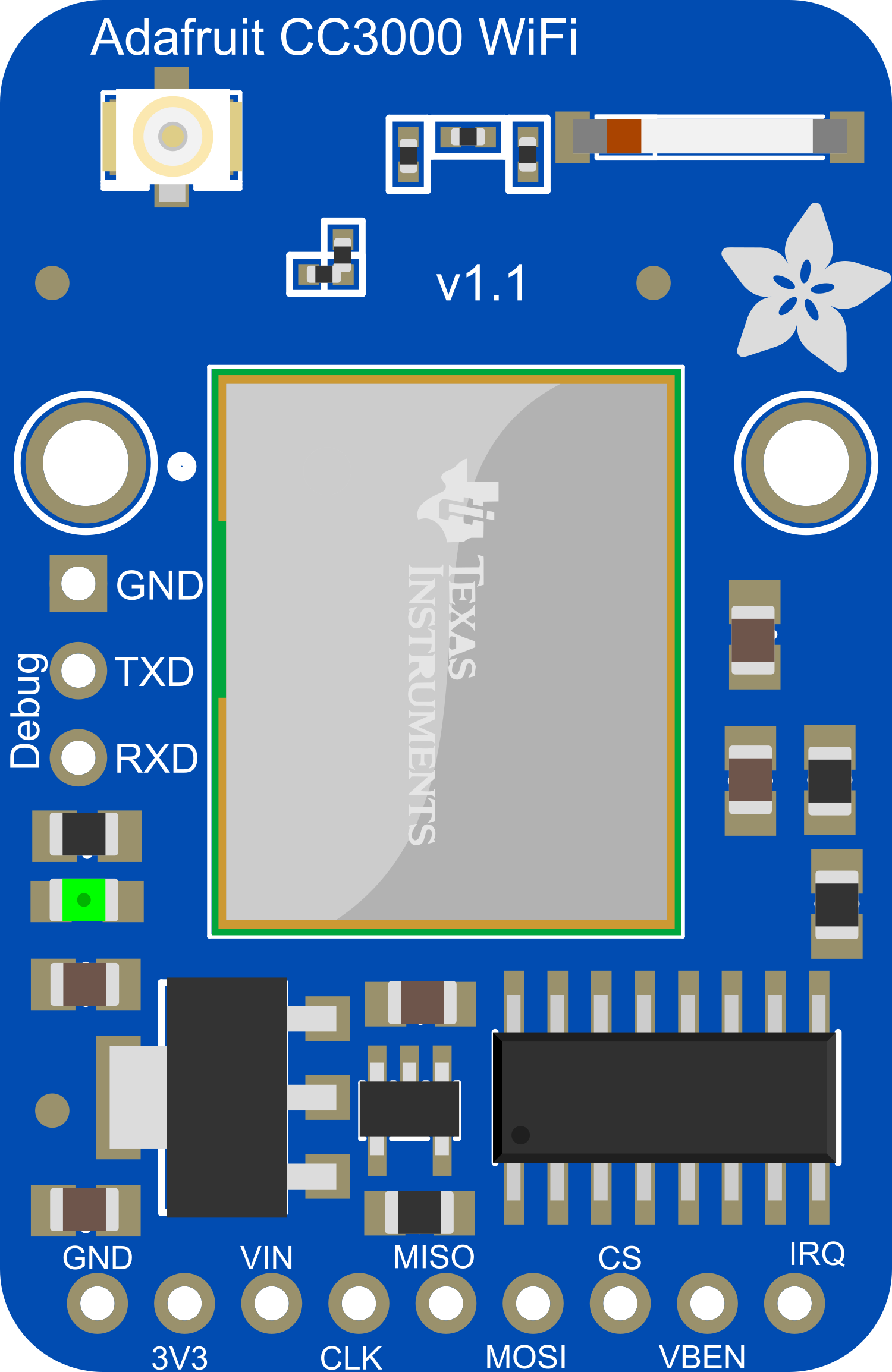
The Adafruit CC3000 WiFi Breakout is a versatile and compact wireless networking module designed to provide Wi-Fi connectivity to microcontroller-based projects. It is based on the CC3000 module from Texas Instruments and is capable of connecting to 802.11b/g networks. This breakout is particularly useful for projects that require internet access or network connectivity, such as home automation systems, IoT devices, and remote data logging.

Explore Projects Built with Adafruit CC3000 WiFi Breakout

Use Cirkit Designer to design, explore, and prototype these projects online. Some projects support real-time simulation. Click "Open Project" to start designing instantly!
Arduino UNO WiFi with Heart Pulse and Temperature Monitoring
Image of BioTrackers: A project utilizing Adafruit CC3000 WiFi Breakout in a practical application
This circuit features an Arduino UNO R4 WiFi microcontroller connected to a Heart Pulse Sensor and an SHT1x-Breakout sensor. The Arduino is configured to read heart pulse signals from the Heart Pulse Sensor on analog pin A0 and temperature/humidity data from the SHT1x-Breakout sensor via the I2C interface on pins A4 (DATA) and A5 (SCK). Both sensors are powered by the Arduino's 5V output, and their ground pins are connected to the Arduino's ground.
Cirkit Designer LogoOpen Project in Cirkit Designer
Arduino UNO R4 WiFi Environmental Data Logger with I2C Multiplexing and SD Storage
Image of scannerII: A project utilizing Adafruit CC3000 WiFi Breakout in a practical application
This circuit features an Arduino UNO R4 WiFi as the central microcontroller, interfaced with a BME280 Breakout sensor for environmental data, an SD card module for data logging, and a TCA9548A I2C multiplexer to manage multiple I2C devices. It also includes a U078-V-M12 sensor and an SPS30 particulate matter sensor, both connected through the I2C multiplexer. Power distribution is managed by a dedicated board that receives 3.3V from the Arduino and distributes it to the SD card module and other components.
Cirkit Designer LogoOpen Project in Cirkit Designer
ESP8266 WiFi Module Serial Interface with Pushbutton Control
Image of esp01 progrmmer: A project utilizing Adafruit CC3000 WiFi Breakout in a practical application
This circuit features an ESP8266 ESP-01 WiFi module interfaced with an Adafruit FTDI Friend for serial communication. The ESP8266's TXD and RXD pins are connected to the FTDI's RX and TX pins respectively, allowing for data exchange between the microcontroller and a computer. Additionally, a pushbutton is connected to the ESP8266's reset pin, enabling manual resets of the module.
Cirkit Designer LogoOpen Project in Cirkit Designer
ESP8266 NodeMCU with ADXL335 Accelerometer and Buzzer Alert System
Image of gps: A project utilizing Adafruit CC3000 WiFi Breakout in a practical application
This circuit features an ESP8266 NodeMCU microcontroller connected to an ADXL335 accelerometer and a buzzer. The accelerometer's VCC and GND are connected to the NodeMCU's 3V3 and GND for power, while its X-OUT pin is connected to the NodeMCU's analog input A0 for motion sensing. The buzzer is controlled by the NodeMCU through digital pin D5, and shares a common ground with the microcontroller.
Cirkit Designer LogoOpen Project in Cirkit Designer

Explore Projects Built with Adafruit CC3000 WiFi Breakout

Use Cirkit Designer to design, explore, and prototype these projects online. Some projects support real-time simulation. Click "Open Project" to start designing instantly!
Image of BioTrackers: A project utilizing Adafruit CC3000 WiFi Breakout in a practical application
Arduino UNO WiFi with Heart Pulse and Temperature Monitoring
This circuit features an Arduino UNO R4 WiFi microcontroller connected to a Heart Pulse Sensor and an SHT1x-Breakout sensor. The Arduino is configured to read heart pulse signals from the Heart Pulse Sensor on analog pin A0 and temperature/humidity data from the SHT1x-Breakout sensor via the I2C interface on pins A4 (DATA) and A5 (SCK). Both sensors are powered by the Arduino's 5V output, and their ground pins are connected to the Arduino's ground.
Cirkit Designer LogoOpen Project in Cirkit Designer
Image of scannerII: A project utilizing Adafruit CC3000 WiFi Breakout in a practical application
Arduino UNO R4 WiFi Environmental Data Logger with I2C Multiplexing and SD Storage
This circuit features an Arduino UNO R4 WiFi as the central microcontroller, interfaced with a BME280 Breakout sensor for environmental data, an SD card module for data logging, and a TCA9548A I2C multiplexer to manage multiple I2C devices. It also includes a U078-V-M12 sensor and an SPS30 particulate matter sensor, both connected through the I2C multiplexer. Power distribution is managed by a dedicated board that receives 3.3V from the Arduino and distributes it to the SD card module and other components.
Cirkit Designer LogoOpen Project in Cirkit Designer
Image of esp01 progrmmer: A project utilizing Adafruit CC3000 WiFi Breakout in a practical application
ESP8266 WiFi Module Serial Interface with Pushbutton Control
This circuit features an ESP8266 ESP-01 WiFi module interfaced with an Adafruit FTDI Friend for serial communication. The ESP8266's TXD and RXD pins are connected to the FTDI's RX and TX pins respectively, allowing for data exchange between the microcontroller and a computer. Additionally, a pushbutton is connected to the ESP8266's reset pin, enabling manual resets of the module.
Cirkit Designer LogoOpen Project in Cirkit Designer
Image of gps: A project utilizing Adafruit CC3000 WiFi Breakout in a practical application
ESP8266 NodeMCU with ADXL335 Accelerometer and Buzzer Alert System
This circuit features an ESP8266 NodeMCU microcontroller connected to an ADXL335 accelerometer and a buzzer. The accelerometer's VCC and GND are connected to the NodeMCU's 3V3 and GND for power, while its X-OUT pin is connected to the NodeMCU's analog input A0 for motion sensing. The buzzer is controlled by the NodeMCU through digital pin D5, and shares a common ground with the microcontroller.
Cirkit Designer LogoOpen Project in Cirkit Designer

Common Applications and Use Cases

  • Internet of Things (IoT) devices
  • Home automation systems
  • Remote sensor monitoring
  • Wireless data logging
  • Robotics with remote control or telemetry

Technical Specifications

Key Technical Details

  • Wi-Fi Standards: IEEE 802.11 b/g
  • Security: WEP, WPA2 (personal)
  • Frequency Band: 2.4 GHz
  • Antenna: Integrated PCB antenna and u.FL connector for external antenna
  • Interface: SPI
  • Input Voltage: 3.3V to 5V DC
  • Current Consumption: ~100 mA during active data transmission

Pin Configuration and Descriptions

Pin Number Name Description
1 VIN Power supply (3.3V to 5V DC)
2 GND Ground connection
3 SCK SPI clock
4 MISO SPI Master In Slave Out
5 MOSI SPI Master Out Slave In
6 CS SPI Chip Select
7 VBEN Optional power control, enables module when high
8 IRQ Interrupt request, active low

Usage Instructions

How to Use the Component in a Circuit

  1. Power Supply: Connect the VIN pin to a 3.3V to 5V DC power source and the GND pin to the ground.
  2. SPI Interface: Connect the SCK, MISO, MOSI, and CS pins to the corresponding SPI pins on your microcontroller.
  3. Interrupt Request: Connect the IRQ pin to an interrupt-capable GPIO pin on your microcontroller.
  4. Optional Power Control: If used, connect the VBEN pin to a GPIO pin to control the power state of the module.

Important Considerations and Best Practices

  • Ensure that the power supply is stable and within the specified voltage range.
  • Use a level shifter if your microcontroller operates at a voltage higher than 3.3V.
  • Place the module away from metal objects and interference sources for optimal signal strength.
  • Update the CC3000 firmware to the latest version for improved performance and compatibility.

Example Code for Arduino UNO

#include <Adafruit_CC3000.h>
#include <ccspi.h>
#include <SPI.h>

// Define the pins for the CC3000 module
#define ADAFRUIT_CC3000_IRQ   3  // Must be an interrupt pin
#define ADAFRUIT_CC3000_VBAT  5
#define ADAFRUIT_CC3000_CS    10

// Create an instance of the Adafruit_CC3000 class
Adafruit_CC3000 cc3000 = Adafruit_CC3000(ADAFRUIT_CC3000_CS, ADAFRUIT_CC3000_IRQ,
                                         ADAFRUIT_CC3000_VBAT, SPI_CLOCK_DIVIDER);

void setup() {
  Serial.begin(115200);
  Serial.println(F("Initializing the CC3000..."));

  // Initialize the CC3000 (SPI clock speed must be set to 16 MHz)
  if (!cc3000.begin()) {
    Serial.println(F("Unable to initialize the CC3000! Check your wiring?"));
    while (1);
  }
  
  // Connect to the Wi-Fi network (replace 'ssid' and 'password')
  if (!cc3000.connectToAP("ssid", "password", WLAN_SEC_WPA2)) {
    Serial.println(F("Failed to connect to WiFi. Please verify credentials"));
    while (1);
  }
  
  Serial.println(F("Connected!"));
  
  // ... Additional code to use the network ...
}

void loop() {
  // Your main code here
}

Code Comments

  • The #include directives at the beginning include the necessary libraries for the CC3000.
  • The #define statements set the pins used for the IRQ, VBEN, and CS connections.
  • The Adafruit_CC3000 object is initialized with the pins defined earlier.
  • In the setup() function, the CC3000 is initialized and an attempt is made to connect to a Wi-Fi network.
  • Replace 'ssid' and 'password' with your actual Wi-Fi credentials.
  • The loop() function is where you would place the code that runs continuously.

Troubleshooting and FAQs

Common Issues

  • Module not responding: Ensure that the wiring is correct and that the power supply is within the specified range.
  • Unable to connect to Wi-Fi: Verify that the SSID and password are correct. Ensure that the Wi-Fi network is 2.4 GHz as the CC3000 does not support 5 GHz networks.
  • Intermittent connectivity: Check for sources of interference and consider using an external antenna if the signal strength is weak.

Solutions and Tips for Troubleshooting

  • Always use the latest library and firmware for the CC3000 module.
  • Use serial output to debug and track the status of Wi-Fi connections.
  • Reset the module and microcontroller if changes to the network settings are made.

FAQs

Q: Can the CC3000 connect to 5 GHz Wi-Fi networks? A: No, the CC3000 only supports 2.4 GHz Wi-Fi networks.

Q: Does the CC3000 support Wi-Fi Protected Setup (WPS)? A: No, the CC3000 does not support WPS. Network credentials must be entered manually.

Q: Can I use the CC3000 with a battery? A: Yes, as long as the battery can provide a stable voltage within the 3.3V to 5V range and can supply sufficient current for operation.