How to Use Touch Sensor TTP233: Examples, Pinouts, and Specs
Introduction
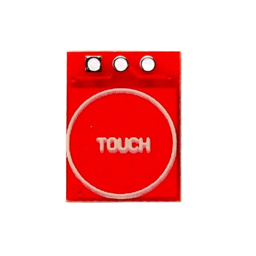
The TTP233 is a capacitive touch sensor switch manufactured by Adafruit (Part ID: sensor). It is designed to detect touch input and can serve as a replacement for traditional mechanical switches. This component is highly sensitive, consumes minimal power, and is easy to integrate into a wide range of electronic projects. Its compact design and reliable performance make it ideal for applications requiring touch-based input.
Explore Projects Built with Touch Sensor TTP233
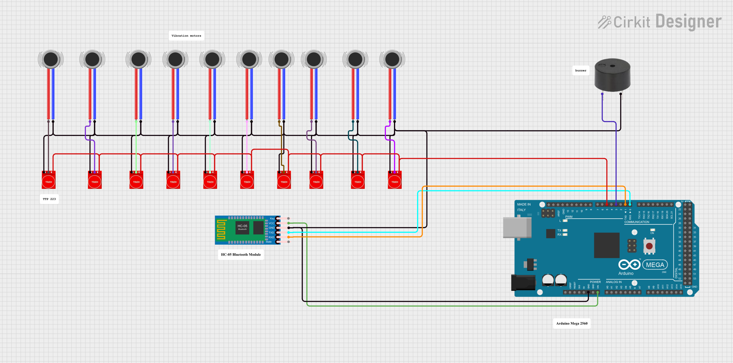
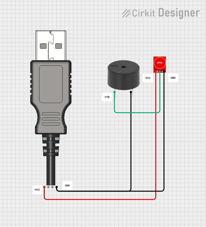
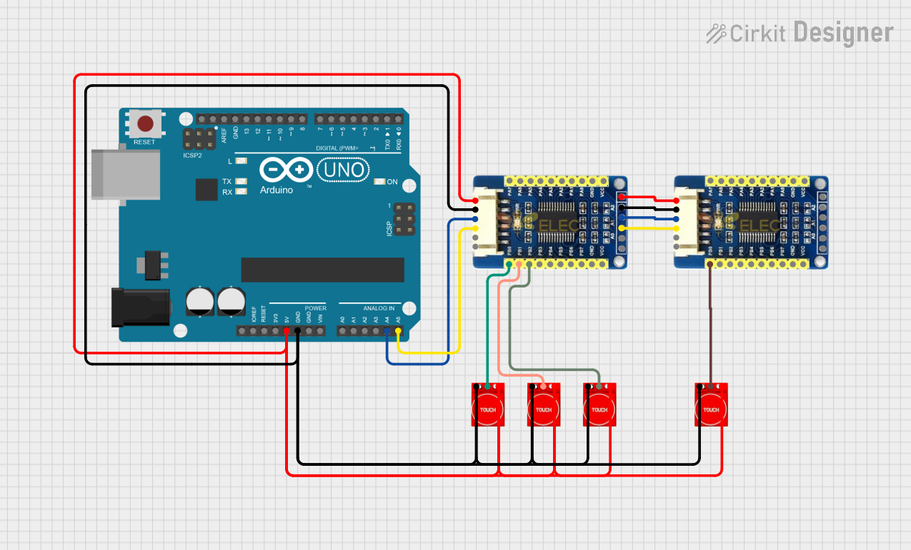

Explore Projects Built with Touch Sensor TTP233
Common Applications and Use Cases
- Touch-sensitive buttons for home automation systems
- Interactive displays and control panels
- Wearable devices and IoT projects
- Replacement for mechanical switches in consumer electronics
- Prototyping touch-based user interfaces
Technical Specifications
The TTP233 touch sensor is a versatile component with the following key specifications:
| Parameter | Value |
|---|---|
| Operating Voltage | 2.0V to 5.5V |
| Operating Current | < 8µA (at 3V, no load) |
| Response Time | ~60ms (fast mode) |
| Output Type | Digital (Active Low) |
| Output Drive Capability | Up to 8mA |
| Touch Sensitivity | Adjustable via external capacitor |
| Operating Temperature | -40°C to +85°C |
| Dimensions | 11mm x 10mm x 1.5mm |
Pin Configuration and Descriptions
The TTP233 touch sensor typically comes in an 8-pin SOP package. Below is the pinout and description:
| Pin | Name | Description |
|---|---|---|
| 1 | VDD | Power supply input (2.0V to 5.5V). Connect to the positive terminal of the power source. |
| 2 | OUT | Digital output pin. Outputs LOW when touch is detected, HIGH otherwise. |
| 3 | AHLB | Active High/Low selection. Connect to GND for active low output. |
| 4 | MODE | Mode selection pin. Connect to GND for fast mode or VDD for low-power mode. |
| 5 | TTPAD | Touch pad input. Connect to a conductive surface to detect touch. |
| 6 | VSS | Ground pin. Connect to the negative terminal of the power source. |
| 7 | NC | No connection. Leave unconnected. |
| 8 | NC | No connection. Leave unconnected. |
Usage Instructions
How to Use the TTP233 in a Circuit
- Power Supply: Connect the VDD pin to a 2.0V–5.5V power source and the VSS pin to ground.
- Touch Pad: Attach a conductive surface (e.g., copper foil) to the TTPAD pin to act as the touch-sensitive area.
- Output: Connect the OUT pin to a microcontroller or other digital input device to read the touch status.
- Mode Selection:
- For fast response, connect the MODE pin to GND.
- For low-power operation, connect the MODE pin to VDD.
- Active Output Selection:
- For active low output, connect the AHLB pin to GND.
- For active high output, connect the AHLB pin to VDD.
Important Considerations and Best Practices
- Capacitor Selection: Use a 0.1µF capacitor between VDD and VSS for power supply decoupling.
- Touch Pad Design: Ensure the touch pad is large enough for reliable detection but not too large to avoid false triggers.
- Environmental Factors: Avoid placing the sensor near sources of electrical noise or moisture, as these can affect performance.
- Pull-up Resistor: If the OUT pin is connected to a microcontroller, ensure the microcontroller's input pin is configured with a pull-up resistor if required.
Example: Connecting to an Arduino UNO
Below is an example of how to connect and use the TTP233 with an Arduino UNO:
Circuit Connections
- VDD: Connect to the 5V pin on the Arduino.
- VSS: Connect to the GND pin on the Arduino.
- OUT: Connect to digital pin 2 on the Arduino.
- TTPAD: Connect to a conductive touch surface.
- MODE: Connect to GND for fast mode.
- AHLB: Connect to GND for active low output.
Arduino Code
// TTP233 Touch Sensor Example with Arduino UNO
// This code reads the touch sensor's output and turns on an LED when touched.

#define TOUCH_SENSOR_PIN 2  // Pin connected to the OUT pin of TTP233
#define LED_PIN 13          // Pin connected to the onboard LED

void setup() {
  pinMode(TOUCH_SENSOR_PIN, INPUT); // Set touch sensor pin as input
  pinMode(LED_PIN, OUTPUT);         // Set LED pin as output
  digitalWrite(LED_PIN, LOW);       // Turn off LED initially
}

void loop() {
  int touchState = digitalRead(TOUCH_SENSOR_PIN); // Read touch sensor state

  if (touchState == LOW) { // Sensor outputs LOW when touched
    digitalWrite(LED_PIN, HIGH); // Turn on LED
  } else {
    digitalWrite(LED_PIN, LOW);  // Turn off LED
  }
}
Troubleshooting and FAQs
Common Issues and Solutions
Sensor Not Responding:
- Ensure the power supply voltage is within the specified range (2.0V–5.5V).
- Check all connections, especially the VDD and VSS pins.
- Verify that the touch pad is properly connected to the TTPAD pin.
False Triggers:
- Reduce environmental noise by adding a capacitor (e.g., 10nF) between the TTPAD pin and ground.
- Ensure the touch pad is not too large or placed near conductive materials.
Output Signal Not Detected:
- Confirm the AHLB pin is correctly configured for the desired active output type.
- Check the pull-up resistor configuration if connected to a microcontroller.
FAQs
Q: Can the TTP233 detect multiple touches simultaneously?
A: No, the TTP233 is designed to detect a single touch at a time.
Q: How can I adjust the sensitivity of the sensor?
A: The sensitivity can be adjusted by changing the value of the capacitor connected to the TTPAD pin. Increasing the capacitance increases sensitivity.
Q: Is the TTP233 suitable for outdoor use?
A: The TTP233 is not waterproof and should be protected from moisture and extreme environmental conditions.
Q: Can I use the TTP233 with a 3.3V microcontroller?
A: Yes, the TTP233 operates within a voltage range of 2.0V to 5.5V, making it compatible with 3.3V systems.