
How to Use Dual Op-Amp: Examples, Pinouts, and Specs
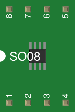
 Design with Dual Op-Amp in Cirkit Designer
Introduction
The Dual Op-Amp (Part ID: Dual Op-Amp SO-8) is an integrated circuit that houses two independent, high-gain operational amplifiers. These amplifiers are designed to amplify voltage signals and are widely used in analog signal processing, filtering, and computational applications. The dual op-amp is versatile and can be configured for various purposes, including summing amplifiers, differential amplifiers, inverting amplifiers, and more.
Explore Projects Built with Dual Op-Amp
 Open Project in Cirkit Designer
 Open Project in Cirkit Designer
 Open Project in Cirkit Designer
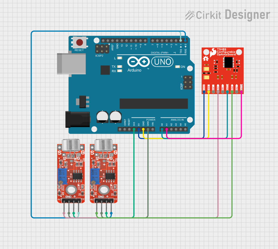 Open Project in Cirkit Designer
Explore Projects Built with Dual Op-Amp
Open Project in Cirkit DesignerOpen Project in Cirkit DesignerOpen Project in Cirkit DesignerOpen Project in Cirkit DesignerCommon Applications
- Signal amplification in audio and instrumentation systems
- Active filters (low-pass, high-pass, band-pass)
- Analog computation (e.g., addition, subtraction, integration, differentiation)
- Voltage followers (buffer circuits)
- Oscillators and waveform generators
Technical Specifications
Key Technical Details
| Parameter | Value |
|---|---|
| Supply Voltage (Vcc) | ±3V to ±18V |
| Input Offset Voltage | Typically 2mV |
| Input Bias Current | Typically 20nA |
| Gain Bandwidth Product | 1 MHz |
| Slew Rate | 0.5 V/µs |
| Output Voltage Swing | ±(Vcc - 1.5V) |
| Operating Temperature | -40°C to +85°C |
| Package Type | SO-8 (Small Outline Package) |
Pin Configuration and Descriptions
The Dual Op-Amp SO-8 package has 8 pins, as described in the table below:
| Pin Number | Pin Name | Description |
|---|---|---|
| 1 | Output A | Output of the first operational amplifier |
| 2 | Inverting A | Inverting input of the first operational amplifier |
| 3 | Non-Inverting A | Non-inverting input of the first operational amplifier |
| 4 | V- (GND) | Negative power supply or ground |
| 5 | Non-Inverting B | Non-inverting input of the second operational amplifier |
| 6 | Inverting B | Inverting input of the second operational amplifier |
| 7 | Output B | Output of the second operational amplifier |
| 8 | V+ (Vcc) | Positive power supply |
Usage Instructions
How to Use the Dual Op-Amp in a Circuit
- Power Supply: Connect the positive power supply (V+) to pin 8 and the negative power supply (V-) or ground to pin 4. Ensure the supply voltage is within the specified range (±3V to ±18V).
- Input Connections: Connect the input signals to the inverting (pins 2 and 6) or non-inverting (pins 3 and 5) terminals, depending on the desired configuration (e.g., inverting or non-inverting amplifier).
- Output Connections: The amplified signal will be available at the output pins (pins 1 and 7). Connect these to the next stage of your circuit.
- Feedback Resistors: Use appropriate resistors or components in the feedback loop to set the gain and behavior of the amplifier.
Example: Non-Inverting Amplifier Circuit
Below is an example of using the Dual Op-Amp with an Arduino UNO to amplify an analog signal.
Circuit Diagram
- Connect the non-inverting input (pin 3) to the signal source.
- Connect a resistor (R1) between the inverting input (pin 2) and ground.
- Connect a resistor (R2) between the output (pin 1) and the inverting input (pin 2).
- The gain of the amplifier is given by: Gain = 1 + (R2 / R1).
Arduino Code Example
// Example: Reading an amplified signal using Arduino UNO
// Connect the output of the op-amp to Arduino's analog pin A0

void setup() {
  Serial.begin(9600); // Initialize serial communication at 9600 baud
}

void loop() {
  int sensorValue = analogRead(A0); // Read the amplified signal
  float voltage = sensorValue * (5.0 / 1023.0); // Convert to voltage
  Serial.print("Amplified Voltage: ");
  Serial.println(voltage); // Print the voltage to the Serial Monitor
  delay(500); // Wait for 500ms before the next reading
}
Important Considerations
- Power Supply Decoupling: Place decoupling capacitors (e.g., 0.1µF and 10µF) close to the power supply pins to reduce noise.
- Input Impedance: Ensure the source impedance matches the op-amp's input impedance for optimal performance.
- Thermal Management: Operate the op-amp within the specified temperature range to avoid thermal issues.
- Stability: Use compensation capacitors if required to prevent oscillations in high-gain configurations.
Troubleshooting and FAQs
Common Issues and Solutions
No Output Signal:
- Verify the power supply connections (V+ and V-).
- Check for proper input signal connections.
- Ensure feedback components (resistors, capacitors) are correctly placed.
Distorted Output:
- Ensure the input signal amplitude is within the op-amp's input voltage range.
- Check if the output is saturating due to excessive gain or insufficient supply voltage.
Oscillations or Noise:
- Add decoupling capacitors near the power supply pins.
- Use proper grounding techniques to minimize noise.
Low Gain or Incorrect Amplification:
- Verify the values of feedback resistors (R1 and R2).
- Ensure the circuit configuration matches the intended design (e.g., inverting vs. non-inverting).
FAQs
Q1: Can I use the Dual Op-Amp with a single power supply?
Yes, the Dual Op-Amp can operate with a single supply voltage. In this case, connect V- to ground and ensure the input signals are biased within the op-amp's input voltage range.
Q2: What is the maximum output current of the Dual Op-Amp?
The maximum output current is typically around 20mA. Exceeding this limit may damage the device.
Q3: Can I use the Dual Op-Amp for audio applications?
Yes, the Dual Op-Amp is suitable for audio signal amplification, provided the gain and bandwidth requirements are met.
Q4: How do I calculate the gain for an inverting amplifier?
For an inverting amplifier, the gain is given by: Gain = - (R2 / R1), where R1 is the resistor connected to the input signal and R2 is the feedback resistor.
By following this documentation, users can effectively integrate the Dual Op-Amp into their electronic designs for a wide range of applications.