
How to Use AMT103: Examples, Pinouts, and Specs
 Design with AMT103 in Cirkit Designer
Introduction
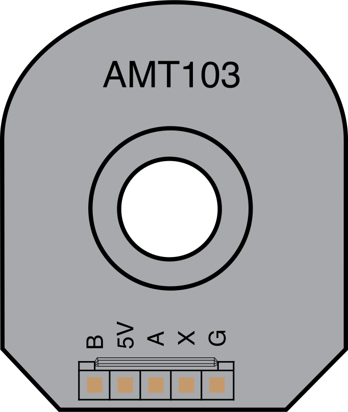
The AMT103 is a non-contact magnetic encoder manufactured by CUI Devices. It is designed to provide precise angular position feedback using a Hall effect sensor to detect the position of a rotating magnet. This encoder is highly reliable and accurate, making it suitable for a wide range of motion control applications.
Explore Projects Built with AMT103
 Open Project in Cirkit Designer
 Open Project in Cirkit Designer
 Open Project in Cirkit Designer
 Open Project in Cirkit Designer
Explore Projects Built with AMT103
Open Project in Cirkit DesignerOpen Project in Cirkit DesignerOpen Project in Cirkit DesignerOpen Project in Cirkit DesignerCommon Applications
- Robotics and automation systems
- Motor control and feedback loops
- Industrial machinery
- Medical devices
- Precision positioning systems
Technical Specifications
The following table outlines the key technical details of the AMT103 encoder:
| Parameter | Value |
|---|---|
| Manufacturer Part ID | AMT103 |
| Operating Voltage | 3.3 V to 5.5 V |
| Current Consumption | 6 mA (typical) |
| Resolution | Configurable: 48 to 2048 PPR |
| Output Signal | Quadrature A/B with Index (Z) |
| Maximum Rotational Speed | 60,000 RPM |
| Operating Temperature Range | -40°C to +125°C |
| Communication Interface | Digital (TTL-compatible) |
| Mounting Options | Modular, with multiple shaft sizes |
Pin Configuration
The AMT103 encoder has a 9-pin connector. The pinout and descriptions are as follows:
| Pin Number | Pin Name | Description |
|---|---|---|
| 1 | VCC | Power supply input (3.3 V to 5.5 V) |
| 2 | GND | Ground connection |
| 3 | A | Quadrature output channel A |
| 4 | B | Quadrature output channel B |
| 5 | Z | Index pulse output |
| 6 | NC | Not connected |
| 7 | NC | Not connected |
| 8 | NC | Not connected |
| 9 | NC | Not connected |
Usage Instructions
How to Use the AMT103 in a Circuit
- Power Supply: Connect the VCC pin to a regulated power source (3.3 V to 5.5 V) and the GND pin to the circuit ground.
- Signal Connections: Connect the A, B, and Z pins to the corresponding inputs of your microcontroller or motor driver. These pins provide the quadrature signals and index pulse for position feedback.
- Mounting: Secure the encoder to the motor shaft using the modular mounting kit provided by the manufacturer. Ensure proper alignment to avoid signal errors.
- Resolution Configuration: Use the configuration tool provided by CUI Devices to set the desired resolution (PPR). Follow the manufacturer's instructions for this step.
Important Considerations
- Signal Integrity: Use shielded cables for the signal lines to minimize noise interference, especially in high-speed or noisy environments.
- Power Supply Stability: Ensure the power supply is stable and within the specified voltage range to avoid erratic behavior.
- Alignment: Proper alignment of the encoder with the motor shaft is critical for accurate position feedback.
- Index Pulse: The Z (index) pulse occurs once per revolution and can be used for homing or reference purposes.
Example: Connecting the AMT103 to an Arduino UNO
Below is an example of how to connect the AMT103 to an Arduino UNO and read the quadrature signals:
Circuit Connections
- Connect the VCC pin of the AMT103 to the 5V pin on the Arduino.
- Connect the GND pin of the AMT103 to the GND pin on the Arduino.
- Connect the A pin of the AMT103 to digital pin 2 on the Arduino.
- Connect the B pin of the AMT103 to digital pin 3 on the Arduino.
Arduino Code
// AMT103 Quadrature Encoder Example
// This code reads the A and B signals from the encoder and calculates position.

#define ENCODER_PIN_A 2  // Connect to AMT103 A pin
#define ENCODER_PIN_B 3  // Connect to AMT103 B pin

volatile int position = 0;  // Variable to store encoder position

void setup() {
  pinMode(ENCODER_PIN_A, INPUT);  // Set A pin as input
  pinMode(ENCODER_PIN_B, INPUT);  // Set B pin as input

  // Attach interrupts to handle encoder signals
  attachInterrupt(digitalPinToInterrupt(ENCODER_PIN_A), handleEncoder, CHANGE);

  Serial.begin(9600);  // Initialize serial communication
}

void loop() {
  // Print the current position to the Serial Monitor
  Serial.print("Position: ");
  Serial.println(position);
  delay(100);  // Delay for readability
}

void handleEncoder() {
  // Read the current state of A and B pins
  int stateA = digitalRead(ENCODER_PIN_A);
  int stateB = digitalRead(ENCODER_PIN_B);

  // Determine direction based on A and B signals
  if (stateA == stateB) {
    position++;  // Clockwise rotation
  } else {
    position--;  // Counterclockwise rotation
  }
}
Notes on the Code
- The code uses interrupts to handle the encoder signals, ensuring accurate position tracking even at high speeds.
- The
positionvariable stores the current position of the encoder. You can modify the code to reset or calibrate this value as needed.
Troubleshooting and FAQs
Common Issues
No Output Signals
- Cause: Incorrect wiring or loose connections.
- Solution: Double-check all connections, especially the VCC and GND pins.
Erratic Position Feedback
- Cause: Noise interference or unstable power supply.
- Solution: Use shielded cables for signal lines and ensure a stable power source.
Incorrect Position Readings
- Cause: Misalignment of the encoder with the motor shaft.
- Solution: Re-align the encoder and ensure it is securely mounted.
Index Pulse Not Detected
- Cause: Improper configuration or missed connection to the Z pin.
- Solution: Verify the Z pin connection and ensure the encoder is configured correctly.
FAQs
Can the AMT103 be used with a 3.3 V microcontroller?
- Yes, the AMT103 operates within a voltage range of 3.3 V to 5.5 V, making it compatible with 3.3 V systems.
What is the purpose of the index pulse (Z)?
- The index pulse provides a single pulse per revolution, which can be used for homing or as a reference point in position tracking.
How do I configure the resolution of the AMT103?
- Use the configuration tool provided by CUI Devices to set the desired resolution. Refer to the manufacturer's documentation for detailed instructions.
What is the maximum rotational speed the AMT103 can handle?
- The AMT103 can operate at speeds up to 60,000 RPM.
By following this documentation, users can effectively integrate the AMT103 encoder into their projects and troubleshoot common issues with ease.