Cirkit Designer Logo
Cirkit Designer
Your all-in-one circuit design IDE
Home / 
Component Documentation

How to Use Motor Servo Analog Output: Examples, Pinouts, and Specs

Image of Motor Servo Analog Output
Cirkit Designer LogoDesign with Motor Servo Analog Output in Cirkit Designer

Introduction

The Motor Servo Analog Output is a type of servo motor that operates using an analog signal to control its position. Unlike digital servos, which rely on pulse-width modulation (PWM) signals, analog servos respond to continuous voltage changes to adjust their position. These servos are widely used in robotics, RC vehicles, and automation systems due to their simplicity and reliability.

Explore Projects Built with Motor Servo Analog Output

Use Cirkit Designer to design, explore, and prototype these projects online. Some projects support real-time simulation. Click "Open Project" to start designing instantly!
Arduino UNO Controlled Servo with Potentiometer Positioning
Image of Servo: A project utilizing Motor Servo Analog Output in a practical application
This circuit consists of an Arduino UNO microcontroller connected to a servo motor and a potentiometer. The potentiometer's output is connected to an analog input (A0) on the Arduino to provide variable control, likely for the servo position. The servo is controlled by a digital output (D5) from the Arduino, and both the servo and potentiometer are powered by the Arduino's 5V supply with a common ground.
Cirkit Designer LogoOpen Project in Cirkit Designer
Arduino-Controlled Robotic System with Vision and Distance Sensing
Image of FYP: A project utilizing Motor Servo Analog Output in a practical application
This circuit appears to be a servo motor control system with multiple servo motors of different torque ratings, powered by a 12V/30A DC power supply through DC-to-DC converters. It includes an Arduino UNO and an Arduino Nano for control logic, interfaced with an MPU-6050 for motion sensing and two vl53l0xv2 sensors for distance measurement. Additionally, there is an ESP32-CAM module for image capture and a laser diode, likely for positioning or targeting, all orchestrated by embedded code running on the microcontrollers.
Cirkit Designer LogoOpen Project in Cirkit Designer
Arduino Mega 2560 Controlled Multi-Servo Random Positioning System
Image of robotic: A project utilizing Motor Servo Analog Output in a practical application
This circuit consists of an Arduino Mega 2560 microcontroller connected to twelve servo motors, each individually controlled by a distinct PWM pin on the Arduino. The servos are powered by a single Polymer Lithium Ion Battery, with all servos sharing a common power (VCC) and ground (GND) connection. The embedded code on the Arduino is designed to randomly position each servo within a 0 to 180-degree range, with a random delay between movements, demonstrating a multi-servo control system possibly for applications like robotics or animatronics.
Cirkit Designer LogoOpen Project in Cirkit Designer
Arduino UNO Servo Control System
Image of servo motor: A project utilizing Motor Servo Analog Output in a practical application
This circuit consists of an Arduino UNO microcontroller that is programmed to control a servo motor. The servo is powered by the 5V output from the Arduino and receives pulse-width modulation (PWM) signals on its control line from digital pin D9 of the Arduino. The code on the Arduino sets the servo to rotate between 90 and 180 degrees with a delay of 1 second between movements.
Cirkit Designer LogoOpen Project in Cirkit Designer

Explore Projects Built with Motor Servo Analog Output

Use Cirkit Designer to design, explore, and prototype these projects online. Some projects support real-time simulation. Click "Open Project" to start designing instantly!
Image of Servo: A project utilizing Motor Servo Analog Output in a practical application
Arduino UNO Controlled Servo with Potentiometer Positioning
This circuit consists of an Arduino UNO microcontroller connected to a servo motor and a potentiometer. The potentiometer's output is connected to an analog input (A0) on the Arduino to provide variable control, likely for the servo position. The servo is controlled by a digital output (D5) from the Arduino, and both the servo and potentiometer are powered by the Arduino's 5V supply with a common ground.
Cirkit Designer LogoOpen Project in Cirkit Designer
Image of FYP: A project utilizing Motor Servo Analog Output in a practical application
Arduino-Controlled Robotic System with Vision and Distance Sensing
This circuit appears to be a servo motor control system with multiple servo motors of different torque ratings, powered by a 12V/30A DC power supply through DC-to-DC converters. It includes an Arduino UNO and an Arduino Nano for control logic, interfaced with an MPU-6050 for motion sensing and two vl53l0xv2 sensors for distance measurement. Additionally, there is an ESP32-CAM module for image capture and a laser diode, likely for positioning or targeting, all orchestrated by embedded code running on the microcontrollers.
Cirkit Designer LogoOpen Project in Cirkit Designer
Image of robotic: A project utilizing Motor Servo Analog Output in a practical application
Arduino Mega 2560 Controlled Multi-Servo Random Positioning System
This circuit consists of an Arduino Mega 2560 microcontroller connected to twelve servo motors, each individually controlled by a distinct PWM pin on the Arduino. The servos are powered by a single Polymer Lithium Ion Battery, with all servos sharing a common power (VCC) and ground (GND) connection. The embedded code on the Arduino is designed to randomly position each servo within a 0 to 180-degree range, with a random delay between movements, demonstrating a multi-servo control system possibly for applications like robotics or animatronics.
Cirkit Designer LogoOpen Project in Cirkit Designer
Image of servo motor: A project utilizing Motor Servo Analog Output in a practical application
Arduino UNO Servo Control System
This circuit consists of an Arduino UNO microcontroller that is programmed to control a servo motor. The servo is powered by the 5V output from the Arduino and receives pulse-width modulation (PWM) signals on its control line from digital pin D9 of the Arduino. The code on the Arduino sets the servo to rotate between 90 and 180 degrees with a delay of 1 second between movements.
Cirkit Designer LogoOpen Project in Cirkit Designer

Common Applications and Use Cases

  • Robotics: For controlling arms, grippers, and joints.
  • Remote-controlled vehicles: Steering and throttle control.
  • Automation systems: Positioning mechanisms in industrial equipment.
  • Educational projects: Demonstrating motion control concepts.

Technical Specifications

Key Technical Details

  • Operating Voltage: 4.8V to 6.0V
  • Operating Current: 100mA to 500mA (depending on load)
  • Torque: 1.5 kg·cm to 10 kg·cm (varies by model)
  • Signal Type: Analog voltage (typically 0V to 5V)
  • Rotation Range: 0° to 180° (standard), 360° for continuous rotation models
  • Response Time: ~0.2 seconds per 60° (at 6.0V)
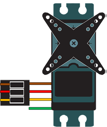
  • Connector Type: 3-pin (Signal, VCC, GND)

Pin Configuration and Descriptions

Pin Name Description Wire Color (Typical)
Signal Receives the analog control signal Orange or White
VCC Power supply (4.8V to 6.0V) Red
GND Ground connection Black or Brown

Usage Instructions

How to Use the Component in a Circuit

  1. Power the Servo: Connect the VCC pin to a 5V power source and the GND pin to the ground of your circuit.
  2. Control Signal: Connect the Signal pin to an analog output pin of your microcontroller or a potentiometer for manual control.
  3. Load Considerations: Ensure the servo's torque rating is sufficient for the load it will move. Overloading the servo can cause overheating or failure.
  4. Power Supply: Use a dedicated power supply for the servo if it draws significant current, as this can prevent voltage drops in your circuit.

Important Considerations and Best Practices

  • Avoid Overloading: Do not exceed the torque rating of the servo to prevent damage.
  • Stable Power Supply: Use capacitors near the servo to stabilize the power supply and reduce noise.
  • Analog Signal Range: Ensure the control signal voltage matches the servo's specifications (typically 0V to 5V).
  • Avoid Continuous Stalling: Prolonged stalling can overheat the motor and reduce its lifespan.

Example: Connecting to an Arduino UNO

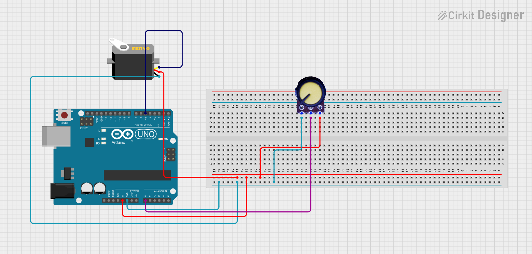
Below is an example of how to control a Motor Servo Analog Output using an Arduino UNO and a potentiometer.

Circuit Connections

  • Connect the servo's Signal pin to Arduino pin A0.
  • Connect the servo's VCC pin to the Arduino's 5V pin.
  • Connect the servo's GND pin to the Arduino's GND pin.
  • Connect a potentiometer to Arduino pin A1 for manual control.

Arduino Code

#include <Servo.h> // Include the Servo library

Servo myServo; // Create a Servo object

void setup() {
  myServo.attach(A0); // Attach the servo to pin A0
}

void loop() {
  int potValue = analogRead(A1); // Read the potentiometer value
  int angle = map(potValue, 0, 1023, 0, 180); 
  // Map the potentiometer value to a range of 0 to 180 degrees
  
  myServo.write(angle); // Set the servo position
  delay(15); // Small delay for smooth movement
}

Troubleshooting and FAQs

Common Issues and Solutions

  1. Servo Not Moving:

    • Cause: Incorrect wiring or insufficient power supply.
    • Solution: Double-check the connections and ensure the power supply meets the servo's requirements.
  2. Jittery Movement:

    • Cause: Electrical noise or unstable power supply.
    • Solution: Add a capacitor (e.g., 100µF) across the VCC and GND pins to stabilize the voltage.
  3. Overheating:

    • Cause: Continuous stalling or overloading.
    • Solution: Reduce the load on the servo or use a higher-torque model.
  4. Limited Range of Motion:

    • Cause: Incorrect signal range or mechanical obstruction.
    • Solution: Verify the control signal range and check for physical obstructions.

FAQs

  • Can I use a digital PWM signal with this servo? No, this servo is designed for analog voltage control. Using a PWM signal may result in erratic behavior.

  • What happens if I exceed the voltage rating? Exceeding the voltage rating can damage the servo's internal circuitry. Always stay within the specified range.

  • Can I control multiple servos with one microcontroller? Yes, but ensure the power supply can handle the combined current draw of all servos.

  • How do I know if the servo is overloaded? Signs of overloading include reduced movement speed, jittering, or overheating. Reduce the load or use a higher-torque servo.