Cirkit Designer Logo
Cirkit Designer
Your all-in-one circuit design IDE
Home / 
Component Documentation

How to Use Pressure Tranducer: Examples, Pinouts, and Specs

Image of Pressure Tranducer
Cirkit Designer LogoDesign with Pressure Tranducer in Cirkit Designer

Introduction

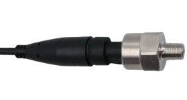
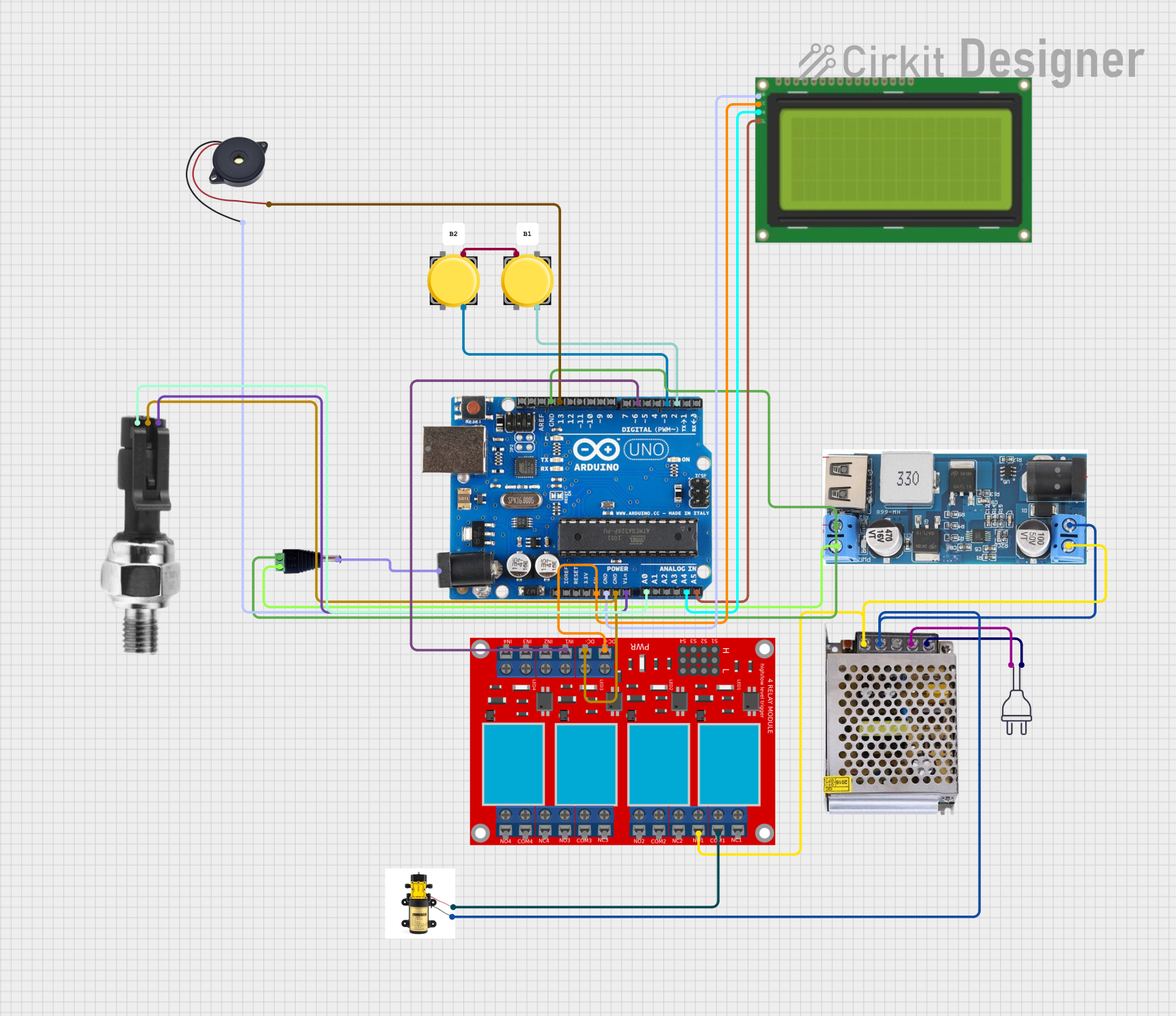
The Pressure Transducer (Manufacturer Part ID: Pressure Transducer) by Arduino is a device designed to convert pressure into an electrical signal. This component is widely used in industrial, automotive, and environmental monitoring applications to measure and control pressure levels with high accuracy and reliability.

Common applications include:

  • Monitoring fluid or gas pressure in pipelines.
  • Measuring atmospheric pressure in weather stations.
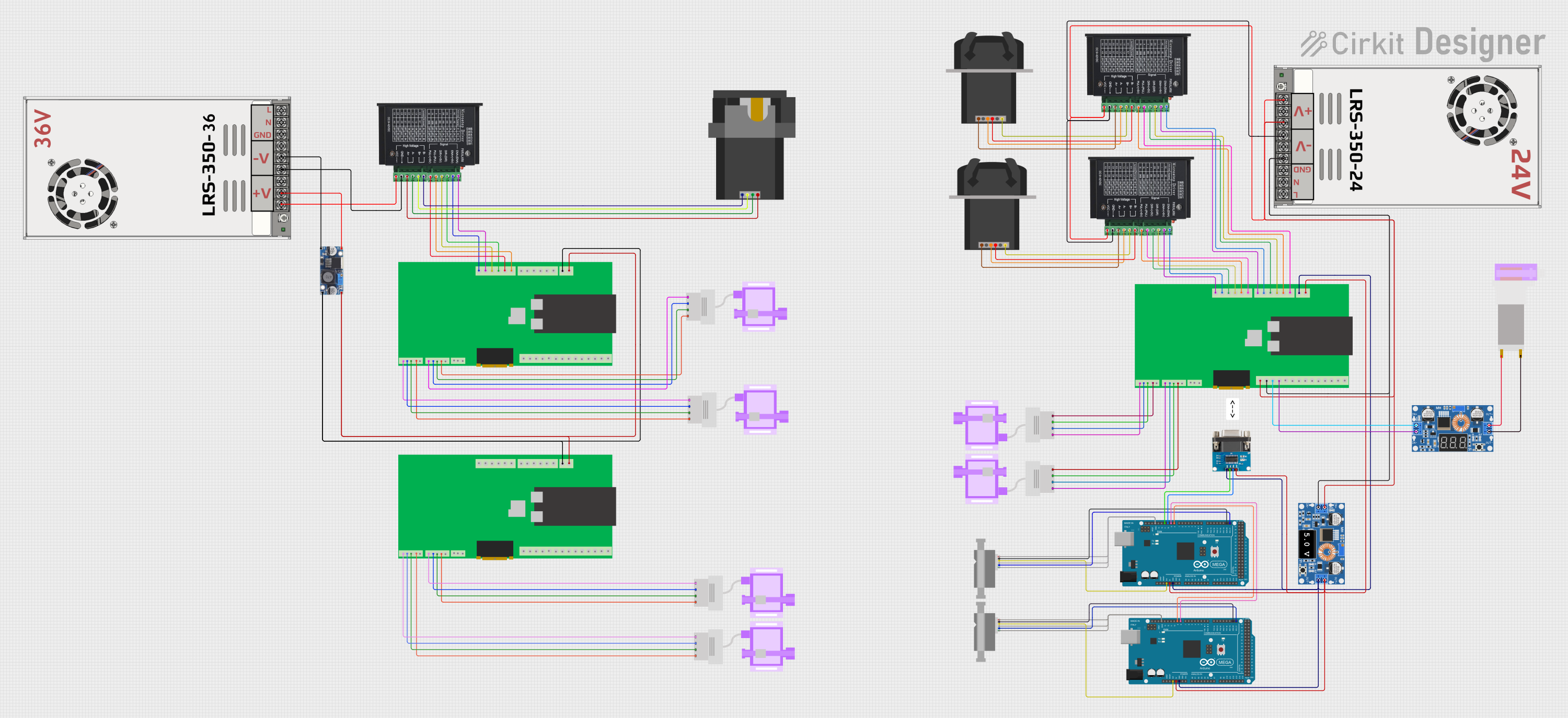
  • Controlling hydraulic or pneumatic systems.
  • Integrating into IoT systems for real-time pressure monitoring.

Explore Projects Built with Pressure Tranducer

Use Cirkit Designer to design, explore, and prototype these projects online. Some projects support real-time simulation. Click "Open Project" to start designing instantly!
ESP32-Controlled Pressure Monitoring System with ADS1115 and Darlington Transistor Switching
Image of Pressuer Sensor Test Rig: A project utilizing Pressure Tranducer in a practical application
This circuit is designed to measure pressure using a transducer, convert the analog signal to digital with an ADS1115 ADC, and process and display the data on an ESP32 microcontroller with a 7-inch screen. It includes power regulation and filtering, as well as a Darlington transistor for load control.
Cirkit Designer LogoOpen Project in Cirkit Designer
Pressure Monitoring System with Voltmeter and Power Supply
Image of PT Test: A project utilizing Pressure Tranducer in a practical application
This circuit measures the output voltage of a pressure transducer using a voltmeter. The pressure transducer is powered by a power supply, and its output voltage is connected to the voltmeter for measurement.
Cirkit Designer LogoOpen Project in Cirkit Designer
ESP32 and Arduino Mega 2560 Controlled Peristaltic Pump System with Pressure and Flow Sensors
Image of Blood & Dialysate Control Bench: A project utilizing Pressure Tranducer in a practical application
This circuit is designed for fluid control and monitoring, featuring multiple peristaltic pumps driven by TB6600 micro-stepping motor drivers, and pressure sensors interfaced with custom PCBs containing ESP32 microcontrollers. It also includes flow meters connected to Arduino Mega 2560 boards for precise flow rate measurement, with power management handled by DC-DC converters and power supplies.
Cirkit Designer LogoOpen Project in Cirkit Designer
Arduino-Based Automatic Tyre Inflator with LCD Display and Pressure Sensor
Image of Arduino based automatic Tire inflator - rush: A project utilizing Pressure Tranducer in a practical application
This circuit is an automated tire inflator system controlled by an Arduino Uno. It uses an industrial pressure sensor to monitor tire pressure, an LCD to display information, and a relay module to control a pump and solenoid valves for inflating and purging air. The system includes pushbuttons for user input and a buzzer for alerts.
Cirkit Designer LogoOpen Project in Cirkit Designer

Explore Projects Built with Pressure Tranducer

Use Cirkit Designer to design, explore, and prototype these projects online. Some projects support real-time simulation. Click "Open Project" to start designing instantly!
Image of Pressuer Sensor Test Rig: A project utilizing Pressure Tranducer in a practical application
ESP32-Controlled Pressure Monitoring System with ADS1115 and Darlington Transistor Switching
This circuit is designed to measure pressure using a transducer, convert the analog signal to digital with an ADS1115 ADC, and process and display the data on an ESP32 microcontroller with a 7-inch screen. It includes power regulation and filtering, as well as a Darlington transistor for load control.
Cirkit Designer LogoOpen Project in Cirkit Designer
Image of PT Test: A project utilizing Pressure Tranducer in a practical application
Pressure Monitoring System with Voltmeter and Power Supply
This circuit measures the output voltage of a pressure transducer using a voltmeter. The pressure transducer is powered by a power supply, and its output voltage is connected to the voltmeter for measurement.
Cirkit Designer LogoOpen Project in Cirkit Designer
Image of Blood & Dialysate Control Bench: A project utilizing Pressure Tranducer in a practical application
ESP32 and Arduino Mega 2560 Controlled Peristaltic Pump System with Pressure and Flow Sensors
This circuit is designed for fluid control and monitoring, featuring multiple peristaltic pumps driven by TB6600 micro-stepping motor drivers, and pressure sensors interfaced with custom PCBs containing ESP32 microcontrollers. It also includes flow meters connected to Arduino Mega 2560 boards for precise flow rate measurement, with power management handled by DC-DC converters and power supplies.
Cirkit Designer LogoOpen Project in Cirkit Designer
Image of Arduino based automatic Tire inflator - rush: A project utilizing Pressure Tranducer in a practical application
Arduino-Based Automatic Tyre Inflator with LCD Display and Pressure Sensor
This circuit is an automated tire inflator system controlled by an Arduino Uno. It uses an industrial pressure sensor to monitor tire pressure, an LCD to display information, and a relay module to control a pump and solenoid valves for inflating and purging air. The system includes pushbuttons for user input and a buzzer for alerts.
Cirkit Designer LogoOpen Project in Cirkit Designer

Technical Specifications

The following table outlines the key technical details of the Arduino Pressure Transducer:

Parameter Value
Operating Voltage 5V DC
Output Signal 0.5V to 4.5V (analog)
Pressure Range 0 to 100 PSI
Accuracy ±1% of full scale
Operating Temperature -20°C to 85°C
Response Time < 1 ms
Sensor Type Piezoelectric
Connection Type 3-pin interface (VCC, GND, OUT)

Pin Configuration and Descriptions

The Pressure Transducer has a 3-pin interface. The pinout is as follows:

Pin Name Description
1 VCC Power supply input (5V DC)
2 GND Ground connection
3 OUT Analog output signal proportional to pressure input

Usage Instructions

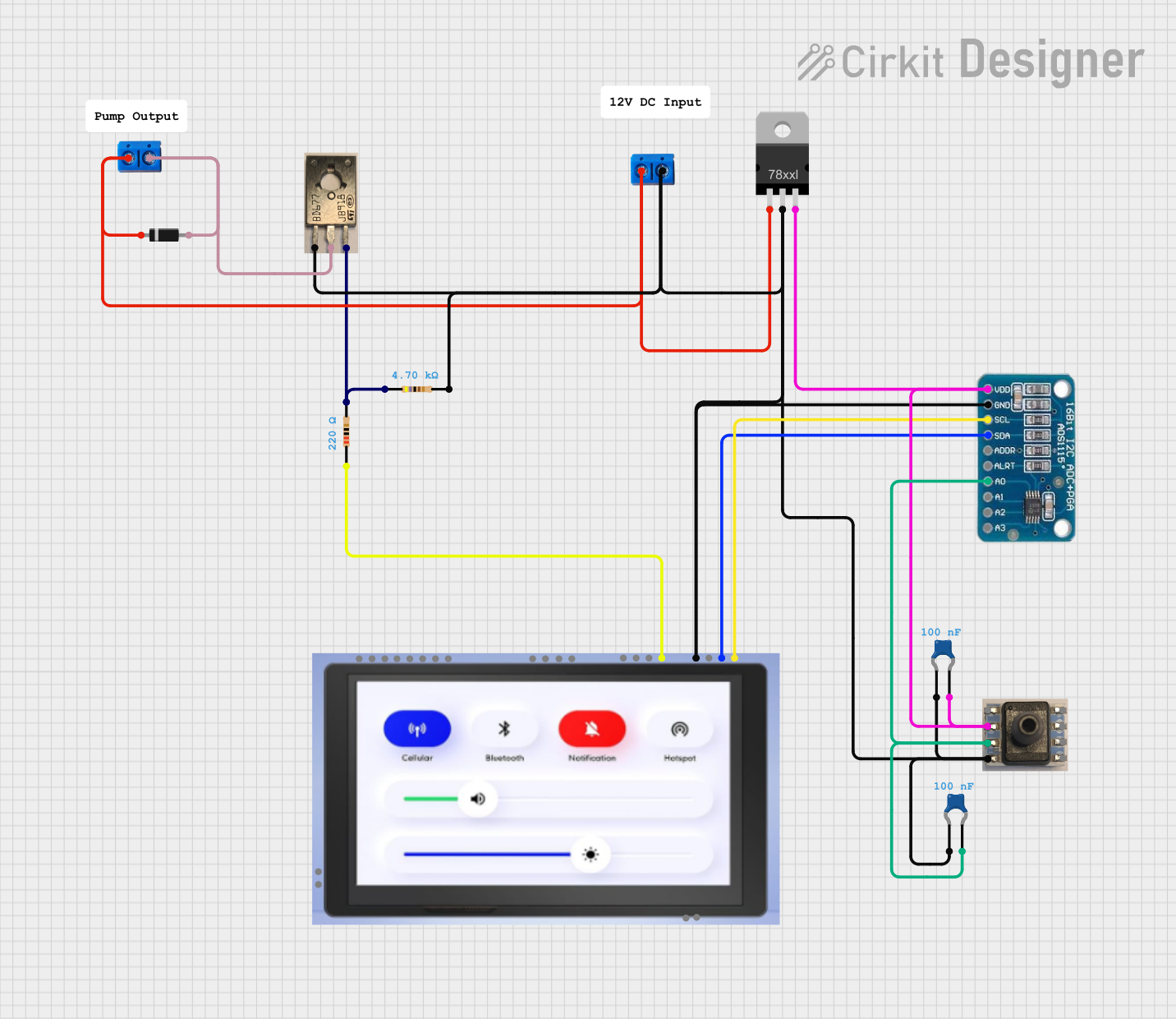
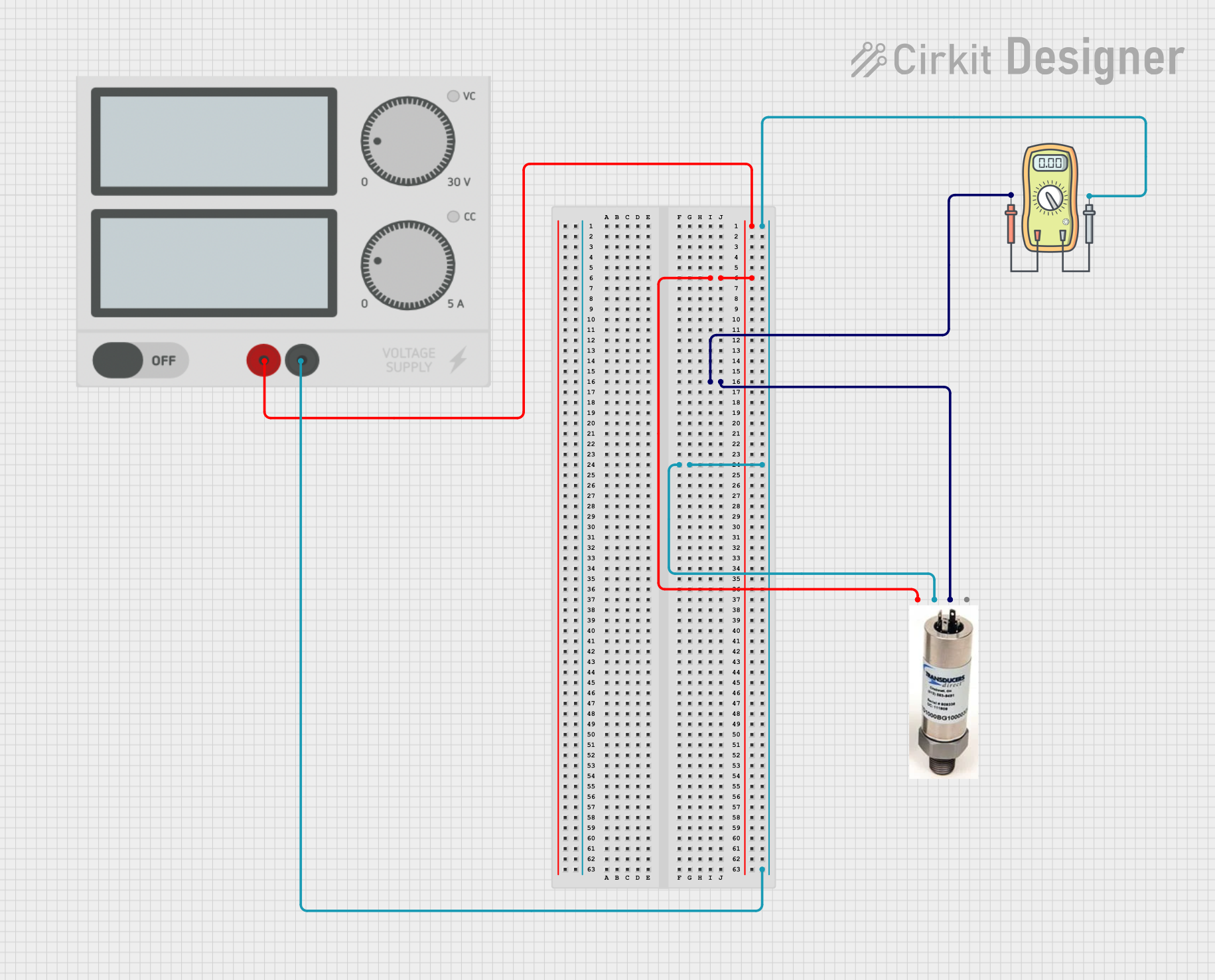
How to Use the Pressure Transducer in a Circuit

  1. Power the Transducer: Connect the VCC pin to a 5V DC power source and the GND pin to the ground of your circuit.
  2. Read the Output Signal: Connect the OUT pin to an analog input pin of a microcontroller (e.g., Arduino UNO) to read the voltage signal corresponding to the pressure.
  3. Calibrate the Sensor: Use the 0.5V to 4.5V output range to map the pressure values. For example:
    • 0.5V corresponds to 0 PSI.
    • 4.5V corresponds to 100 PSI.
  4. Process the Data: Use the microcontroller to convert the analog signal into meaningful pressure readings.

Important Considerations and Best Practices

  • Power Supply: Ensure a stable 5V DC power supply to avoid inaccurate readings.
  • Signal Noise: Use a capacitor (e.g., 0.1 µF) between the OUT pin and GND to filter out noise in the output signal.
  • Pressure Range: Do not exceed the specified pressure range (0 to 100 PSI) to prevent damage to the sensor.
  • Environmental Conditions: Avoid exposing the sensor to temperatures or humidity levels outside its operating range.

Example Code for Arduino UNO

Below is an example code snippet to interface the Pressure Transducer with an Arduino UNO:

// Define the analog pin connected to the Pressure Transducer's OUT pin
const int pressurePin = A0;

// Variables to store sensor readings
float sensorVoltage = 0.0;
float pressure = 0.0;

void setup() {
  // Initialize serial communication for debugging
  Serial.begin(9600);
}

void loop() {
  // Read the analog value from the sensor (0-1023)
  int sensorValue = analogRead(pressurePin);

  // Convert the analog value to voltage (0-5V)
  sensorVoltage = sensorValue * (5.0 / 1023.0);

  // Map the voltage to pressure (0.5V = 0 PSI, 4.5V = 100 PSI)
  pressure = (sensorVoltage - 0.5) * (100.0 / (4.5 - 0.5));

  // Print the pressure value to the Serial Monitor
  Serial.print("Pressure: ");
  Serial.print(pressure);
  Serial.println(" PSI");

  // Delay for a short period before the next reading
  delay(500);
}

Troubleshooting and FAQs

Common Issues and Solutions

  1. No Output Signal:

    • Cause: Incorrect wiring or no power supply.
    • Solution: Verify the connections and ensure the VCC pin is connected to a 5V DC source.
  2. Inaccurate Readings:

    • Cause: Electrical noise or incorrect calibration.
    • Solution: Add a capacitor between the OUT pin and GND to reduce noise. Recheck the calibration formula.
  3. Sensor Damage:

    • Cause: Exceeding the pressure or temperature limits.
    • Solution: Ensure the sensor operates within the specified pressure and temperature ranges.
  4. Fluctuating Output:

    • Cause: Unstable power supply.
    • Solution: Use a regulated 5V DC power source.

FAQs

Q1: Can this sensor measure negative pressure (vacuum)?
A1: No, this sensor is designed to measure positive pressure only, within the range of 0 to 100 PSI.

Q2: Can I use this sensor with a 3.3V microcontroller?
A2: The sensor requires a 5V power supply, but the output signal can be read by a 3.3V microcontroller if the analog input pin supports it. Use a level shifter if needed.

Q3: How do I protect the sensor from overpressure?
A3: Use a pressure relief valve or a mechanical stopper to prevent the pressure from exceeding 100 PSI.

Q4: Is the sensor waterproof?
A4: The sensor is not fully waterproof. Avoid direct exposure to liquids unless the sensor is housed in a protective enclosure.