Cirkit Designer Logo
Cirkit Designer
Your all-in-one circuit design IDE
Home / 
Component Documentation

How to Use 2S 30A BMS: Examples, Pinouts, and Specs

Image of 2S 30A BMS
Cirkit Designer LogoDesign with 2S 30A BMS in Cirkit Designer

Introduction

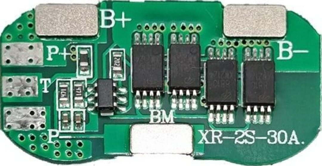
The 2S 30A Battery Management System (BMS) is an essential component designed for managing and protecting 2-series (2S) lithium-ion battery packs. It is capable of handling a maximum continuous current of 30A. The BMS ensures the longevity and safety of the battery pack by preventing overcharging, over-discharging, and by balancing the cells to maintain uniform voltage levels. Common applications include DIY power banks, electric scooters, and portable energy storage systems.

Explore Projects Built with 2S 30A BMS

Use Cirkit Designer to design, explore, and prototype these projects online. Some projects support real-time simulation. Click "Open Project" to start designing instantly!
Battery-Powered Servo Control System with 2S 30A BMS and TP5100 Charger
Image of servo power supply: A project utilizing 2S 30A BMS in a practical application
This circuit is a battery management and charging system for a 2S lithium-ion battery pack, which powers multiple MG996R servos. The TP5100 module charges the battery pack from a 12V power supply, while the 2S 30A BMS ensures safe operation and distribution of power to the servos.
Cirkit Designer LogoOpen Project in Cirkit Designer
Battery-Powered Adjustable Voltage Regulator with Li-ion 18650 Batteries and BMS
Image of mini ups: A project utilizing 2S 30A BMS in a practical application
This circuit is a power management system that uses four Li-ion 18650 batteries connected to a 2S 30A BMS for battery management and protection. The system includes step-up and step-down voltage regulators to provide adjustable output voltages, controlled by a rocker switch, and multiple DC jacks for power input and output.
Cirkit Designer LogoOpen Project in Cirkit Designer
18650 Li-ion Battery Pack with BMS for 5V Power Supply
Image of battary: A project utilizing 2S 30A BMS in a practical application
This circuit consists of a battery management system (BMS) connected to a series of 18650 Li-ion batteries arranged in a 4S configuration to provide a regulated output voltage. The BMS ensures safe charging and discharging of the batteries, while a connector provides a 5V output for external devices.
Cirkit Designer LogoOpen Project in Cirkit Designer
18650 Li-ion Battery Pack with 4S40A BMS and XL4016 Voltage Regulator for Battery-Powered Applications
Image of Power Bank: A project utilizing 2S 30A BMS in a practical application
This circuit is a battery management and charging system for a 4S Li-ion battery pack. It includes multiple 18650 Li-ion batteries connected to a 4S40A BMS for balancing and protection, a battery indicator for monitoring charge status, and an XL4016 module for voltage regulation. The system is designed to be charged via a 20V input from a charger.
Cirkit Designer LogoOpen Project in Cirkit Designer

Explore Projects Built with 2S 30A BMS

Use Cirkit Designer to design, explore, and prototype these projects online. Some projects support real-time simulation. Click "Open Project" to start designing instantly!
Image of servo power supply: A project utilizing 2S 30A BMS in a practical application
Battery-Powered Servo Control System with 2S 30A BMS and TP5100 Charger
This circuit is a battery management and charging system for a 2S lithium-ion battery pack, which powers multiple MG996R servos. The TP5100 module charges the battery pack from a 12V power supply, while the 2S 30A BMS ensures safe operation and distribution of power to the servos.
Cirkit Designer LogoOpen Project in Cirkit Designer
Image of mini ups: A project utilizing 2S 30A BMS in a practical application
Battery-Powered Adjustable Voltage Regulator with Li-ion 18650 Batteries and BMS
This circuit is a power management system that uses four Li-ion 18650 batteries connected to a 2S 30A BMS for battery management and protection. The system includes step-up and step-down voltage regulators to provide adjustable output voltages, controlled by a rocker switch, and multiple DC jacks for power input and output.
Cirkit Designer LogoOpen Project in Cirkit Designer
Image of battary: A project utilizing 2S 30A BMS in a practical application
18650 Li-ion Battery Pack with BMS for 5V Power Supply
This circuit consists of a battery management system (BMS) connected to a series of 18650 Li-ion batteries arranged in a 4S configuration to provide a regulated output voltage. The BMS ensures safe charging and discharging of the batteries, while a connector provides a 5V output for external devices.
Cirkit Designer LogoOpen Project in Cirkit Designer
Image of Power Bank: A project utilizing 2S 30A BMS in a practical application
18650 Li-ion Battery Pack with 4S40A BMS and XL4016 Voltage Regulator for Battery-Powered Applications
This circuit is a battery management and charging system for a 4S Li-ion battery pack. It includes multiple 18650 Li-ion batteries connected to a 4S40A BMS for balancing and protection, a battery indicator for monitoring charge status, and an XL4016 module for voltage regulation. The system is designed to be charged via a 20V input from a charger.
Cirkit Designer LogoOpen Project in Cirkit Designer

Technical Specifications

Key Technical Details

  • Battery Configuration: 2S (2 in series)
  • Voltage Range: 6V - 8.4V (typical operating range for 2S Li-ion batteries)
  • Maximum Continuous Current: 30A
  • Charge/Discharge Cycles: Enhances battery life by managing cycles efficiently
  • Balancing Current: Up to 60mA (typical for cell balancing)
  • Operating Temperature: -20°C to 70°C

Pin Configuration and Descriptions

Pin Number Description Notes
1 B- (Battery Negative) Connect to battery negative terminal
2 P- (Load Negative) Connect to load negative/charging negative
3 C- (Charging Negative) Connect to charging port negative if separate from P-
4 B1+ (Cell 1 Positive) Connect to the positive terminal of the first cell
5 B2+ (Battery Positive) Connect to battery positive terminal

Usage Instructions

Integrating the BMS into a Circuit

  1. Battery Connection: Connect the BMS B- pin to the negative terminal of the battery pack. Connect B1+ to the positive terminal of the first cell, and B2+ to the positive terminal of the second cell.
  2. Load Connection: Connect the load's negative wire to the P- pin of the BMS. The positive wire of the load should be connected directly to the battery's positive terminal.
  3. Charging Connection: If using the same port for charging and discharging, connect the charger's negative wire to P-. If a separate charging port is used, connect the charger's negative wire to C-.

Important Considerations and Best Practices

  • Current Rating: Ensure that the load does not exceed the BMS's maximum continuous current rating of 30A.
  • Temperature: Operate the BMS within the specified temperature range to prevent damage.
  • Mounting: Secure the BMS in a location that minimizes exposure to moisture and extreme temperatures.
  • Wiring: Use appropriate gauge wires to handle the maximum current without overheating.

Troubleshooting and FAQs

Common Issues

  • BMS Not Balancing: Ensure all connections are secure and the cells are within the operational voltage range.
  • Overcurrent Protection Tripping: Check if the load exceeds 30A or if there is a short circuit.

Solutions and Tips

  • Secure Connections: Loose connections can cause voltage drops and erratic BMS behavior.
  • Regular Inspection: Periodically check the BMS and battery pack for signs of wear or damage.

FAQs

Q: Can the BMS be used for batteries other than lithium-ion? A: No, this BMS is specifically designed for 2S lithium-ion battery packs.

Q: What happens if the BMS detects an overcharge condition? A: The BMS will disconnect the charging circuit to prevent further charging and potential damage.

Q: Can I bypass the BMS for a higher current application? A: Bypassing the BMS is not recommended as it removes critical protection features and can lead to battery damage or failure.

Example Arduino Code

If you're using the BMS with an Arduino-based project to monitor the battery status, here's a simple code snippet to get you started:

// Define the analog pin connected to the battery voltage divider
const int batteryPin = A0;

void setup() {
  // Begin serial communication at 9600 baud rate
  Serial.begin(9600);
}

void loop() {
  // Read the voltage from the battery
  int sensorValue = analogRead(batteryPin);
  // Convert the reading to voltage (for a 3.3V Arduino)
  float voltage = sensorValue * (3.3 / 1023.0) * 2; // Multiply by 2 for voltage divider
  
  // Print the voltage to the Serial Monitor
  Serial.print("Battery Voltage: ");
  Serial.println(voltage);
  
  // Wait for a second before taking another reading
  delay(1000);
}

Note: The code assumes a voltage divider is used to step down the battery voltage to a safe level for the Arduino analog input. Adjust the multiplier in the voltage calculation based on your specific voltage divider.

Remember to keep code comments concise and within the 80 character line length limit.