How to Use ESP32 Terminal adapter 38 pin: Examples, Pinouts, and Specs
Introduction
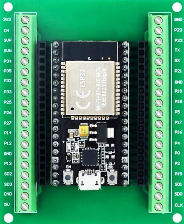
The ESP32 Terminal Adapter 38 Pin is a versatile breakout board designed to simplify the use of the ESP32 microcontroller. Manufactured by ESP, this adapter provides a convenient way to connect the 38 pins of the ESP32 to external peripherals and components. It is particularly useful for prototyping and development, as it allows for easy access to all GPIO pins, power, and communication interfaces.
Explore Projects Built with ESP32 Terminal adapter 38 pin
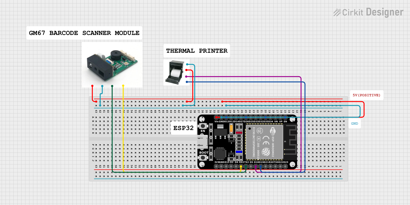

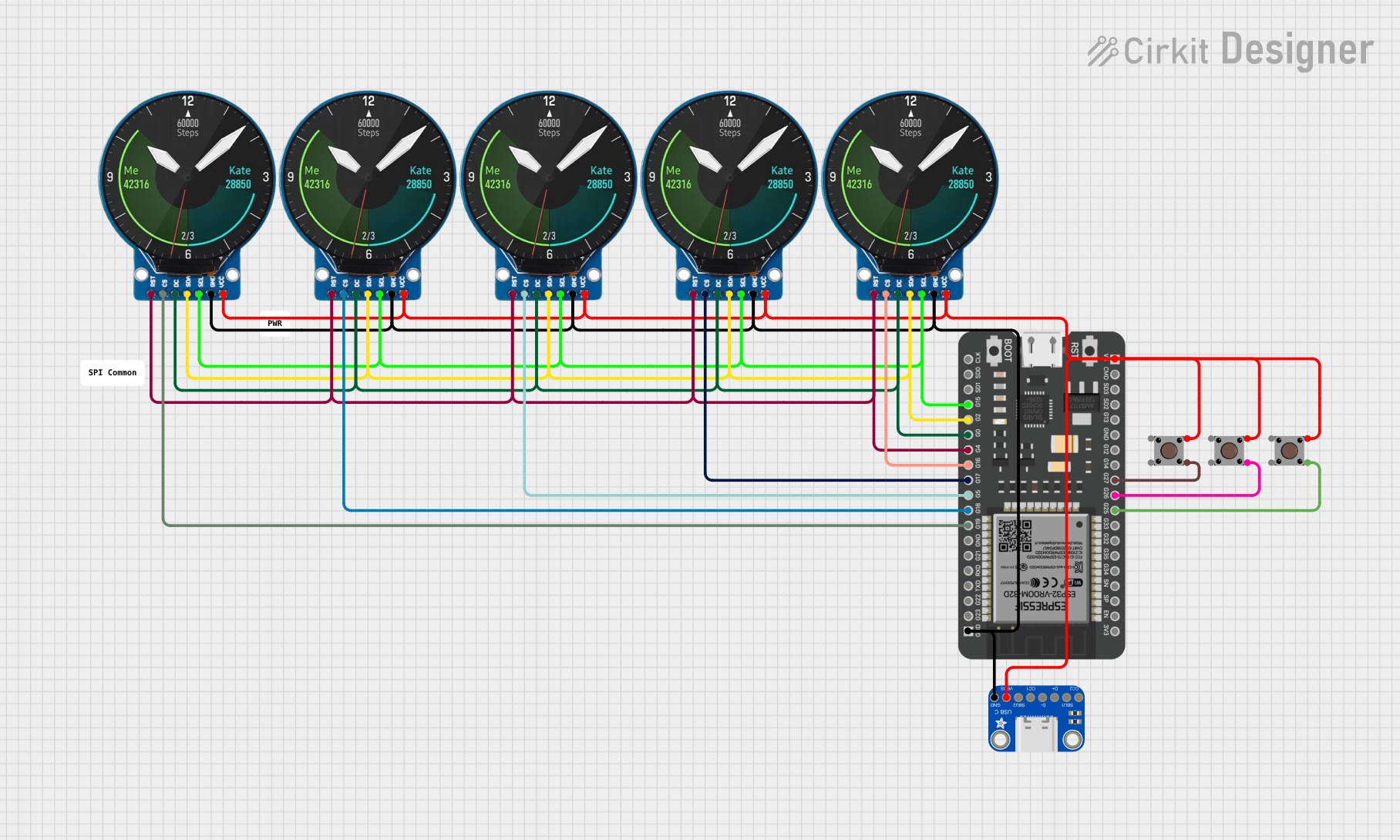

Explore Projects Built with ESP32 Terminal adapter 38 pin
Common Applications and Use Cases
- Rapid prototyping of IoT devices
- Development of smart home automation systems
- Robotics and sensor integration
- Educational projects and learning platforms
- Wireless communication projects using Wi-Fi and Bluetooth
Technical Specifications
The following table outlines the key technical details of the ESP32 Terminal Adapter 38 Pin:
| Parameter | Specification |
|---|---|
| Manufacturer | ESP |
| Part ID | 32 |
| Number of Pins | 38 |
| Supported Microcontroller | ESP32 |
| Input Voltage | 5V (via USB) or 3.3V (via external power supply) |
| Communication Protocols | UART, SPI, I2C, PWM, ADC, DAC |
| Dimensions | 57mm x 25mm x 13mm |
| Mounting Type | Through-hole or breadboard compatible |
Pin Configuration and Descriptions
The ESP32 Terminal Adapter provides access to all 38 pins of the ESP32 microcontroller. Below is a table describing the pin configuration:
| Pin Number | Pin Name | Description |
|---|---|---|
| 1 | GND | Ground |
| 2 | 3V3 | 3.3V Power Output |
| 3 | EN | Enable Pin (Active High) |
| 4 | IO0 | GPIO0, used for boot mode selection |
| 5 | IO1 (TX0) | GPIO1, UART0 Transmit |
| 6 | IO3 (RX0) | GPIO3, UART0 Receive |
| 7 | IO4 | GPIO4, General Purpose I/O |
| 8 | IO5 | GPIO5, General Purpose I/O |
| ... | ... | ... |
| 38 | IO39 | GPIO39, ADC Input |
Note: For the complete pinout, refer to the ESP32 datasheet or pinout diagram.
Usage Instructions
How to Use the ESP32 Terminal Adapter in a Circuit
Powering the Adapter:
- Connect the adapter to a 5V USB power source or supply 3.3V directly to the 3V3 pin.
- Ensure the ground (GND) pin is connected to the circuit's ground.
Connecting Peripherals:
- Use jumper wires to connect sensors, actuators, or other components to the GPIO pins.
- For communication protocols like I2C or SPI, connect the appropriate pins (e.g., SDA, SCL for I2C).
Programming the ESP32:
- Connect the adapter to your computer via a USB cable.
- Use the Arduino IDE or ESP-IDF to upload code to the ESP32.
Mounting:
- The adapter is breadboard-compatible, making it easy to integrate into prototyping setups.
Important Considerations and Best Practices
- Voltage Levels: Ensure that all connected peripherals operate at 3.3V logic levels to avoid damaging the ESP32.
- Boot Mode: To enter programming mode, hold the BOOT button while pressing the EN (reset) button.
- Pin Usage: Avoid using GPIO pins that are reserved for specific functions (e.g., GPIO0 for boot mode).
Example Code for Arduino UNO Integration
Below is an example of how to use the ESP32 Terminal Adapter with an Arduino UNO to read data from a DHT11 temperature and humidity sensor:
#include <DHT.h>

// Define the DHT sensor type and pin
#define DHTPIN 4 // GPIO4 on the ESP32 Terminal Adapter
#define DHTTYPE DHT11 // DHT11 sensor type

DHT dht(DHTPIN, DHTTYPE);

void setup() {
  Serial.begin(115200); // Initialize serial communication
  dht.begin(); // Initialize the DHT sensor
  Serial.println("DHT11 Sensor Test");
}

void loop() {
  // Read temperature and humidity values
  float humidity = dht.readHumidity();
  float temperature = dht.readTemperature();

  // Check if the readings are valid
  if (isnan(humidity) || isnan(temperature)) {
    Serial.println("Failed to read from DHT sensor!");
    return;
  }

  // Print the readings to the Serial Monitor
  Serial.print("Humidity: ");
  Serial.print(humidity);
  Serial.print("%  Temperature: ");
  Serial.print(temperature);
  Serial.println("°C");

  delay(2000); // Wait 2 seconds before the next reading
}
Note: Ensure the DHT11 sensor is connected to GPIO4, and the appropriate pull-up resistor is used.
Troubleshooting and FAQs
Common Issues and Solutions
ESP32 Not Detected by Computer:
- Ensure the USB cable is functional and supports data transfer.
- Install the correct USB-to-serial driver for the ESP32.
Program Upload Fails:
- Check that the ESP32 is in programming mode (hold BOOT while pressing EN).
- Verify the correct COM port and board settings in the Arduino IDE.
Peripherals Not Responding:
- Double-check the wiring and ensure the peripherals are powered correctly.
- Confirm that the GPIO pins used are not reserved for other functions.
Overheating:
- Ensure the ESP32 is not overloaded with excessive current draw from peripherals.
- Use a heat sink or fan if necessary.
FAQs
Q: Can I use 5V peripherals with the ESP32 Terminal Adapter?
A: No, the ESP32 operates at 3.3V logic levels. Use a level shifter for 5V peripherals.
Q: How do I reset the ESP32?
A: Press the EN button on the terminal adapter to reset the ESP32.
Q: Is the adapter compatible with all ESP32 modules?
A: The adapter is designed for 38-pin ESP32 modules. Ensure your module matches this configuration.
Q: Can I use the adapter for battery-powered projects?
A: Yes, you can power the adapter using a 3.3V battery or a 5V USB power bank.