Cirkit Designer Logo
Cirkit Designer
Your all-in-one circuit design IDE
Home / 
Component Documentation

How to Use Diode (Output Rectifier): Examples, Pinouts, and Specs

Image of Diode (Output Rectifier)
Cirkit Designer LogoDesign with Diode (Output Rectifier) in Cirkit Designer

Introduction

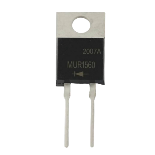
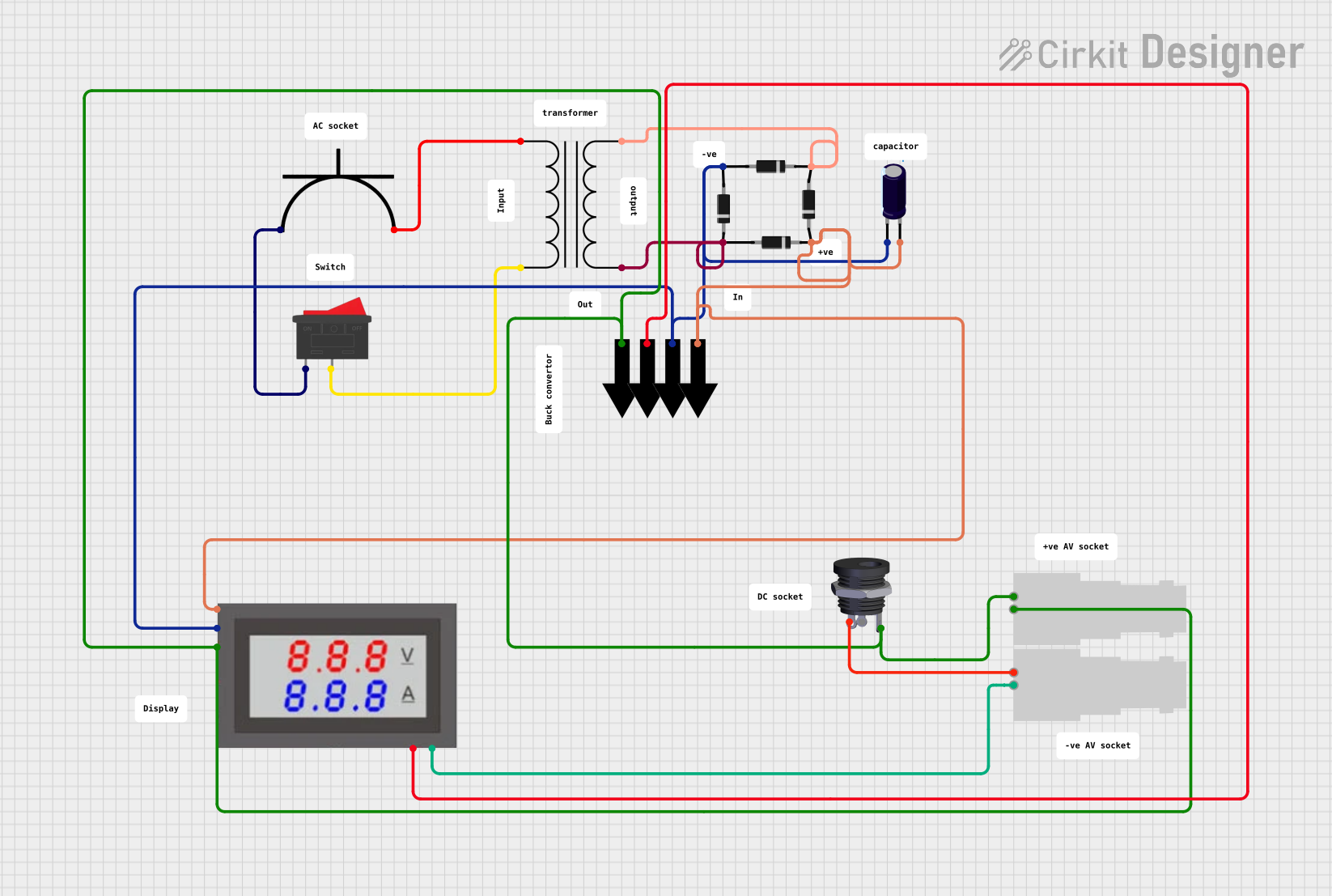
The Diode (Output Rectifier), manufactured by John, is a semiconductor device designed to allow current to flow in one direction only. This component is primarily used in power supply circuits to convert alternating current (AC) into direct current (DC). Its rectification properties make it an essential component in various electronic applications, including power adapters, battery chargers, and DC power supplies.

Explore Projects Built with Diode (Output Rectifier)

Use Cirkit Designer to design, explore, and prototype these projects online. Some projects support real-time simulation. Click "Open Project" to start designing instantly!
AC Power Supply with Diode Rectification and Bulb Indicator
Image of susa: A project utilizing Diode (Output Rectifier) in a practical application
This circuit is a simple AC-powered light with a diode in series. The diode is connected in series with the AC supply's positive terminal and the AC bulb's neutral terminal, while the bulb's positive terminal is connected to the AC supply's negative terminal. The diode will rectify the AC current, allowing only one half of the AC waveform to pass through to the bulb, causing it to flicker at a rate of half the AC frequency.
Cirkit Designer LogoOpen Project in Cirkit Designer
AC to DC Power Supply with Voltage Regulation and LED Indicator
Image of Copy of 8 volt AC to DC convertor (1): A project utilizing Diode (Output Rectifier) in a practical application
This circuit is a basic AC to DC power supply with voltage regulation. It includes a transformer to step down the AC voltage, a bridge rectifier made of 1N4007 diodes to convert AC to DC, an electrolytic capacitor for smoothing, and a voltage regulator to provide a stable DC output. An LED with a current-limiting resistor indicates the presence of the output voltage.
Cirkit Designer LogoOpen Project in Cirkit Designer
Piezo Sensor-Based LED Indicator with Pushbutton Control
Image of project: A project utilizing Diode (Output Rectifier) in a practical application
This circuit is a rectifier and indicator system that uses multiple 1N4007 diodes to rectify an AC signal, a piezo sensor for signal detection, and a pushbutton to control the circuit. The rectified signal is filtered by an electrolytic capacitor and a resistor, and the presence of the signal is indicated by a blue LED.
Cirkit Designer LogoOpen Project in Cirkit Designer
AC to DC Power Supply with Built-In Volt/Ammeter
Image of Variable DC: A project utilizing Diode (Output Rectifier) in a practical application
This circuit appears to be a power supply unit that converts AC voltage to a rectified DC output. It uses a power transformer to step down the AC voltage, which is then rectified by a bridge rectifier composed of four diodes. An electrolytic capacitor is used for smoothing the rectified output, and a mini digital volt/ammeter is included to monitor the voltage and current. The circuit also includes a rocker switch for power control, an AC power plug as the input, and a DC female jack and BNC connectors as outputs.
Cirkit Designer LogoOpen Project in Cirkit Designer

Explore Projects Built with Diode (Output Rectifier)

Use Cirkit Designer to design, explore, and prototype these projects online. Some projects support real-time simulation. Click "Open Project" to start designing instantly!
Image of susa: A project utilizing Diode (Output Rectifier) in a practical application
AC Power Supply with Diode Rectification and Bulb Indicator
This circuit is a simple AC-powered light with a diode in series. The diode is connected in series with the AC supply's positive terminal and the AC bulb's neutral terminal, while the bulb's positive terminal is connected to the AC supply's negative terminal. The diode will rectify the AC current, allowing only one half of the AC waveform to pass through to the bulb, causing it to flicker at a rate of half the AC frequency.
Cirkit Designer LogoOpen Project in Cirkit Designer
Image of Copy of 8 volt AC to DC convertor (1): A project utilizing Diode (Output Rectifier) in a practical application
AC to DC Power Supply with Voltage Regulation and LED Indicator
This circuit is a basic AC to DC power supply with voltage regulation. It includes a transformer to step down the AC voltage, a bridge rectifier made of 1N4007 diodes to convert AC to DC, an electrolytic capacitor for smoothing, and a voltage regulator to provide a stable DC output. An LED with a current-limiting resistor indicates the presence of the output voltage.
Cirkit Designer LogoOpen Project in Cirkit Designer
Image of project: A project utilizing Diode (Output Rectifier) in a practical application
Piezo Sensor-Based LED Indicator with Pushbutton Control
This circuit is a rectifier and indicator system that uses multiple 1N4007 diodes to rectify an AC signal, a piezo sensor for signal detection, and a pushbutton to control the circuit. The rectified signal is filtered by an electrolytic capacitor and a resistor, and the presence of the signal is indicated by a blue LED.
Cirkit Designer LogoOpen Project in Cirkit Designer
Image of Variable DC: A project utilizing Diode (Output Rectifier) in a practical application
AC to DC Power Supply with Built-In Volt/Ammeter
This circuit appears to be a power supply unit that converts AC voltage to a rectified DC output. It uses a power transformer to step down the AC voltage, which is then rectified by a bridge rectifier composed of four diodes. An electrolytic capacitor is used for smoothing the rectified output, and a mini digital volt/ammeter is included to monitor the voltage and current. The circuit also includes a rocker switch for power control, an AC power plug as the input, and a DC female jack and BNC connectors as outputs.
Cirkit Designer LogoOpen Project in Cirkit Designer

Common Applications and Use Cases

  • AC to DC conversion in power supply circuits
  • Voltage regulation and protection
  • Signal demodulation in communication systems
  • Freewheeling diodes in motor control circuits
  • Reverse polarity protection in electronic devices

Technical Specifications

Below are the key technical details for the John Diode (Output Rectifier):

Parameter Value
Maximum Reverse Voltage (VR) 100V - 1000V (varies by model)
Forward Voltage Drop (VF) 0.7V (Silicon) / 0.3V (Schottky)
Maximum Forward Current (IF) 1A - 10A (varies by model)
Peak Surge Current (IFSM) 30A - 150A (varies by model)
Reverse Recovery Time (trr) 50ns - 200ns (varies by model)
Operating Temperature Range -55°C to +150°C

Pin Configuration and Descriptions

The diode has two terminals: Anode and Cathode. The following table describes the pin configuration:

Pin Description
Anode Positive terminal where current enters the diode.
Cathode Negative terminal where current exits the diode.

The cathode is typically marked with a band or stripe on the diode body for easy identification.

Usage Instructions

How to Use the Diode in a Circuit

  1. Identify the Anode and Cathode: Locate the cathode stripe on the diode body to ensure proper orientation.
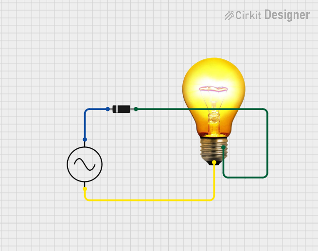
  2. Connect the Diode:
    • For rectification, connect the anode to the AC source and the cathode to the DC load.
    • Ensure the diode is oriented correctly to allow current flow in the desired direction.
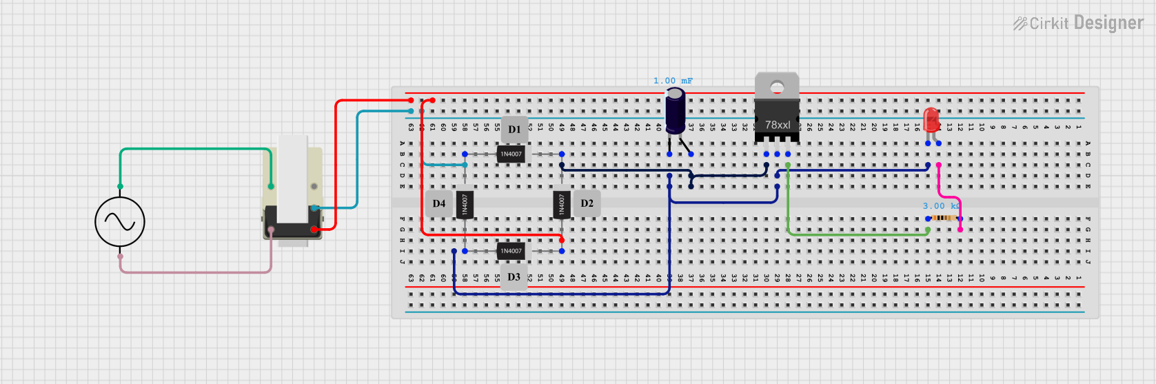
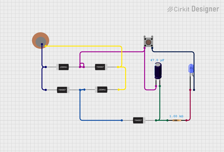
  3. Add Supporting Components:
    • Use a capacitor in parallel with the load to smooth the rectified DC output.
    • For bridge rectifier configurations, use four diodes arranged in a bridge topology.
  4. Verify Ratings:
    • Ensure the diode's voltage and current ratings exceed the circuit's requirements to prevent damage.

Important Considerations and Best Practices

  • Heat Dissipation: High current flow can generate heat. Use a heatsink or ensure proper ventilation if necessary.
  • Reverse Voltage Protection: Avoid exceeding the maximum reverse voltage rating to prevent breakdown.
  • Surge Current: Protect the diode from high inrush currents by using a series resistor or inrush current limiter.
  • Testing: Use a multimeter in diode mode to verify the diode's functionality before installation.

Example: Using a Diode with an Arduino UNO

The diode can be used to protect an Arduino UNO from reverse polarity. Below is an example circuit and code:

Circuit Description

  • Place the diode in series with the Arduino's power input (VIN pin).
  • Connect the anode to the power source and the cathode to the Arduino's VIN pin.

Arduino Code Example

// Example code to blink an LED connected to pin 13
// Ensure the diode protects the Arduino from reverse polarity

void setup() {
  pinMode(13, OUTPUT); // Set pin 13 as an output
}

void loop() {
  digitalWrite(13, HIGH); // Turn the LED on
  delay(1000);            // Wait for 1 second
  digitalWrite(13, LOW);  // Turn the LED off
  delay(1000);            // Wait for 1 second
}

Troubleshooting and FAQs

Common Issues and Solutions

  1. Diode Overheating:

    • Cause: Excessive current or insufficient heat dissipation.
    • Solution: Use a diode with a higher current rating or add a heatsink.
  2. No Current Flow:

    • Cause: Incorrect orientation of the diode.
    • Solution: Verify the anode and cathode connections.
  3. Voltage Drop Too High:

    • Cause: Using a silicon diode instead of a Schottky diode.
    • Solution: Replace with a Schottky diode for lower forward voltage drop.
  4. Diode Failure:

    • Cause: Exceeding reverse voltage or forward current ratings.
    • Solution: Use a diode with appropriate ratings for the application.

FAQs

Q: Can I use this diode for high-frequency applications?
A: Yes, but ensure the reverse recovery time (trr) is suitable for the operating frequency. Schottky diodes are recommended for high-frequency circuits.

Q: How do I test if a diode is working?
A: Use a multimeter in diode mode. A functional diode will show a low voltage drop (e.g., 0.7V for silicon) in the forward direction and no conduction in the reverse direction.

Q: Can this diode protect my circuit from reverse polarity?
A: Yes, place the diode in series with the power supply to block reverse current flow.

By following this documentation, you can effectively use the John Diode (Output Rectifier) in your electronic projects.