How to Use Arduino UNO R3: Examples, Pinouts, and Specs
Introduction
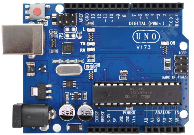
The Arduino UNO R3, manufactured by Arduino, is a microcontroller board based on the ATmega328P. It features 14 digital input/output pins (6 of which can be used as PWM outputs), 6 analog inputs, a USB connection for programming, a power jack, an ICSP header, and a reset button. The board is designed to be user-friendly and is widely used for prototyping, educational purposes, and building interactive electronic projects.
Common applications of the Arduino UNO R3 include:
- Robotics and automation
- IoT (Internet of Things) devices
- Sensor-based systems
- LED control and lighting projects
- Educational tools for learning programming and electronics
Explore Projects Built with Arduino UNO R3
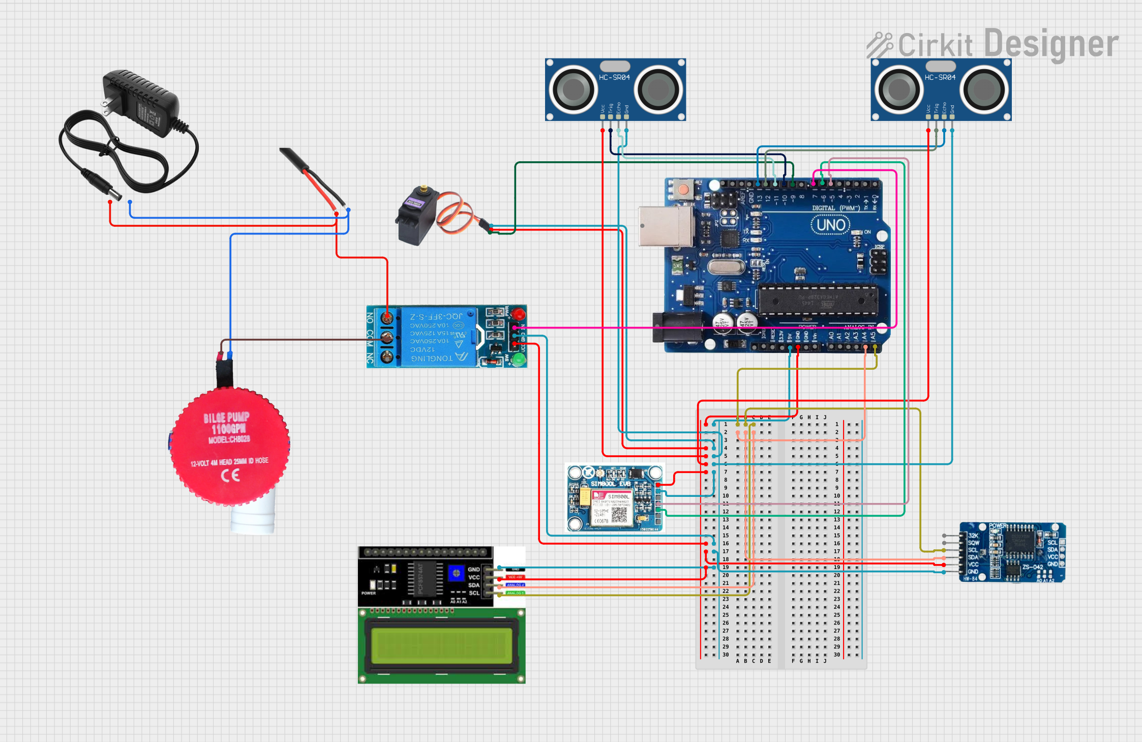
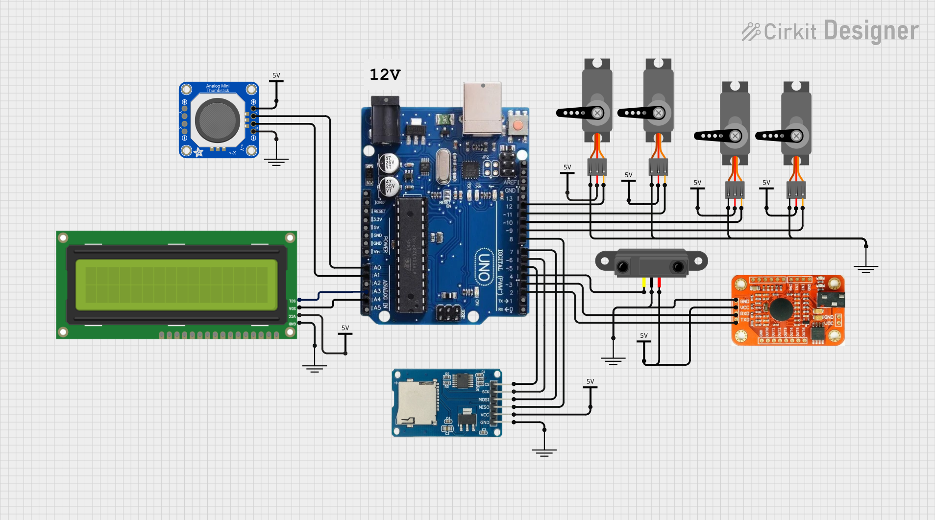
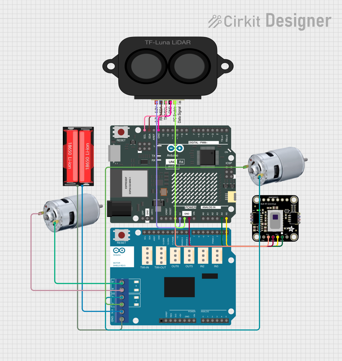
Explore Projects Built with Arduino UNO R3
Technical Specifications
The Arduino UNO R3 is a versatile and robust microcontroller board. Below are its key technical details:
| Specification | Details |
|---|---|
| Microcontroller | ATmega328P |
| Operating Voltage | 5V |
| Input Voltage (recommended) | 7-12V |
| Input Voltage (limit) | 6-20V |
| Digital I/O Pins | 14 (6 PWM outputs) |
| PWM Digital I/O Pins | 6 |
| Analog Input Pins | 6 |
| DC Current per I/O Pin | 20 mA |
| DC Current for 3.3V Pin | 50 mA |
| Flash Memory | 32 KB (0.5 KB used by bootloader) |
| SRAM | 2 KB |
| EEPROM | 1 KB |
| Clock Speed | 16 MHz |
| USB Connector | Type-B |
| Dimensions | 68.6 mm x 53.4 mm |
| Weight | 25 g |
Pin Configuration and Descriptions
The Arduino UNO R3 has a total of 28 pins, including digital, analog, power, and special-purpose pins. Below is a detailed description of the pin configuration:
Digital Pins
| Pin Number | Function | Description |
|---|---|---|
| 0 (RX) | Digital I/O, Serial Receive | Used for serial communication (UART RX) |
| 1 (TX) | Digital I/O, Serial Transmit | Used for serial communication (UART TX) |
| 2-13 | Digital I/O | General-purpose digital input/output pins |
| 3, 5, 6, 9, 10, 11 | PWM Output | Can output PWM signals for motor control, LEDs, etc. |
Analog Pins
| Pin Number | Function | Description |
|---|---|---|
| A0-A5 | Analog Input | Reads analog signals (0-5V) |
Power Pins
| Pin Name | Function | Description |
|---|---|---|
| VIN | Input Voltage | External power input (7-12V recommended) |
| 5V | Regulated 5V Output | Powers external components |
| 3.3V | Regulated 3.3V Output | Powers low-voltage components |
| GND | Ground | Common ground for the circuit |
| RESET | Reset | Resets the microcontroller |
Usage Instructions
The Arduino UNO R3 is easy to use and program. Follow these steps to get started:
Install the Arduino IDE:
- Download and install the Arduino IDE from the official Arduino website (https://www.arduino.cc/).
- Ensure the correct drivers are installed for the Arduino UNO R3.
Connect the Board:
- Use a USB Type-B cable to connect the Arduino UNO R3 to your computer.
- The board will power on, and the "ON" LED will light up.
Select the Board and Port:
- Open the Arduino IDE.
- Go to
Tools > Boardand select "Arduino UNO." - Go to
Tools > Portand select the port to which the board is connected.
Write and Upload Code:
- Write your code in the Arduino IDE or use an example sketch.
- Click the "Upload" button to upload the code to the board.
Example Code: Blinking an LED
The following example demonstrates how to blink an LED connected to pin 13:
// This example blinks the built-in LED on pin 13 of the Arduino UNO R3.
// The LED will turn on for 1 second and off for 1 second in a loop.

void setup() {
  pinMode(13, OUTPUT); // Set pin 13 as an output pin
}

void loop() {
  digitalWrite(13, HIGH); // Turn the LED on
  delay(1000);            // Wait for 1 second
  digitalWrite(13, LOW);  // Turn the LED off
  delay(1000);            // Wait for 1 second
}
Important Considerations
- Power Supply: Use a regulated power supply within the recommended range (7-12V). Avoid exceeding the 20V limit to prevent damage.
- Pin Current Limits: Do not exceed 20 mA per I/O pin or 50 mA for the 3.3V pin.
- Static Electricity: Handle the board carefully to avoid damage from static discharge.
Troubleshooting and FAQs
Common Issues
The board is not detected by the computer:
- Ensure the USB cable is properly connected and functional.
- Check if the correct drivers are installed.
- Verify that the correct port is selected in the Arduino IDE.
Code upload fails:
- Ensure the correct board ("Arduino UNO") is selected in the IDE.
- Check if the RX and TX LEDs blink during the upload process.
- Press the reset button on the board and try uploading again.
The board does not power on:
- Verify the power source (USB or external) is functioning.
- Check for loose connections or damaged components.
FAQs
Q: Can I power the Arduino UNO R3 with batteries?
A: Yes, you can power the board using a 9V battery connected to the VIN and GND pins or via the DC power jack.
Q: What is the maximum current the board can supply?
A: The 5V pin can supply up to 500 mA when powered via USB, and the 3.3V pin can supply up to 50 mA.
Q: Can I use the Arduino UNO R3 for wireless communication?
A: Yes, you can use external modules like Bluetooth, Wi-Fi, or RF transceivers to enable wireless communication.
Q: How do I reset the board?
A: Press the reset button on the board, or connect the RESET pin to GND momentarily.
By following this documentation, you can effectively use the Arduino UNO R3 for a wide range of projects and applications.