Cirkit Designer Logo
Cirkit Designer
Your all-in-one circuit design IDE
Home / 
Component Documentation

How to Use XT90FEMALE: Examples, Pinouts, and Specs

Image of XT90FEMALE
Cirkit Designer LogoDesign with XT90FEMALE in Cirkit Designer

Introduction

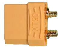
The XT90FEMALE is a high-current connector designed for use in RC (radio-controlled) applications, such as drones, electric vehicles, and high-power battery systems. It features a secure locking mechanism to ensure a reliable connection and is capable of handling up to 90A of continuous current. Its robust design and heat-resistant materials make it ideal for demanding applications where safety and performance are critical.

Explore Projects Built with XT90FEMALE

Use Cirkit Designer to design, explore, and prototype these projects online. Some projects support real-time simulation. Click "Open Project" to start designing instantly!
FTDI to UART Adapter with J26 Connector
Image of J26 CLOSEUP: A project utilizing XT90FEMALE in a practical application
This circuit connects an FTDI USB-to-serial converter to a standard serial interface via a J26 connector. It facilitates serial communication by linking the ground, transmit, receive, data terminal ready, and request to send signals between the FTDI chip and the J26 connector.
Cirkit Designer LogoOpen Project in Cirkit Designer
Satellite-Based Timing and Navigation System with SDR and Atomic Clock Synchronization
Image of GPS 시스템 측정 구성도_Confirm: A project utilizing XT90FEMALE in a practical application
This circuit appears to be a complex system involving power supply management, GPS and timing synchronization, and data communication. It includes a SI-TEX G1 Satellite Compass for GPS data, an XHTF1021 Atomic Rubidium Clock for precise timing, and Ettus USRP B200 units for software-defined radio communication. Power is supplied through various SMPS units and distributed via terminal blocks and DC jacks. Data communication is facilitated by Beelink MINI S12 N95 computers, RS232 splitters, and a 1000BASE-T Media Converter for network connectivity. RF Directional Couplers are used to interface antennas with the USRP units, and the entire system is likely contained within cases for protection and organization.
Cirkit Designer LogoOpen Project in Cirkit Designer
Multi-Channel Load Cell Measurement System with JYS60 Amplifiers and DAQ Integration
Image of Load Cell Circuit: A project utilizing XT90FEMALE in a practical application
This is a multi-channel load cell measurement system with several JYS60 amplifiers connected to load cells for weight or force sensing. The amplified signals are directed to a DAQ system for data capture, and power is supplied through a barrel jack. Grounding is achieved via an AdaGator Side Black component.
Cirkit Designer LogoOpen Project in Cirkit Designer
Beelink Mini S12 N95 and Arduino UNO Based Fingerprint Authentication System with ESP32 CAM
Image of design 3: A project utilizing XT90FEMALE in a practical application
This circuit features a Beelink MINI S12 N95 computer connected to a 7-inch display via HDMI for video output and two USB connections for power and touch screen functionality. An Arduino UNO is interfaced with a fingerprint scanner for biometric input. The Beelink MINI S12 N95 is powered by a PC power supply, which in turn is connected to a 240V power source. Additionally, an ESP32 CAM module is powered and programmed via a USB plug and an FTDI programmer, respectively, for wireless camera capabilities.
Cirkit Designer LogoOpen Project in Cirkit Designer

Explore Projects Built with XT90FEMALE

Use Cirkit Designer to design, explore, and prototype these projects online. Some projects support real-time simulation. Click "Open Project" to start designing instantly!
Image of J26 CLOSEUP: A project utilizing XT90FEMALE in a practical application
FTDI to UART Adapter with J26 Connector
This circuit connects an FTDI USB-to-serial converter to a standard serial interface via a J26 connector. It facilitates serial communication by linking the ground, transmit, receive, data terminal ready, and request to send signals between the FTDI chip and the J26 connector.
Cirkit Designer LogoOpen Project in Cirkit Designer
Image of GPS 시스템 측정 구성도_Confirm: A project utilizing XT90FEMALE in a practical application
Satellite-Based Timing and Navigation System with SDR and Atomic Clock Synchronization
This circuit appears to be a complex system involving power supply management, GPS and timing synchronization, and data communication. It includes a SI-TEX G1 Satellite Compass for GPS data, an XHTF1021 Atomic Rubidium Clock for precise timing, and Ettus USRP B200 units for software-defined radio communication. Power is supplied through various SMPS units and distributed via terminal blocks and DC jacks. Data communication is facilitated by Beelink MINI S12 N95 computers, RS232 splitters, and a 1000BASE-T Media Converter for network connectivity. RF Directional Couplers are used to interface antennas with the USRP units, and the entire system is likely contained within cases for protection and organization.
Cirkit Designer LogoOpen Project in Cirkit Designer
Image of Load Cell Circuit: A project utilizing XT90FEMALE in a practical application
Multi-Channel Load Cell Measurement System with JYS60 Amplifiers and DAQ Integration
This is a multi-channel load cell measurement system with several JYS60 amplifiers connected to load cells for weight or force sensing. The amplified signals are directed to a DAQ system for data capture, and power is supplied through a barrel jack. Grounding is achieved via an AdaGator Side Black component.
Cirkit Designer LogoOpen Project in Cirkit Designer
Image of design 3: A project utilizing XT90FEMALE in a practical application
Beelink Mini S12 N95 and Arduino UNO Based Fingerprint Authentication System with ESP32 CAM
This circuit features a Beelink MINI S12 N95 computer connected to a 7-inch display via HDMI for video output and two USB connections for power and touch screen functionality. An Arduino UNO is interfaced with a fingerprint scanner for biometric input. The Beelink MINI S12 N95 is powered by a PC power supply, which in turn is connected to a 240V power source. Additionally, an ESP32 CAM module is powered and programmed via a USB plug and an FTDI programmer, respectively, for wireless camera capabilities.
Cirkit Designer LogoOpen Project in Cirkit Designer

Common Applications

  • RC vehicles (cars, boats, drones, and planes)
  • High-power lithium battery packs
  • Electric bikes and scooters
  • Solar power systems
  • DIY electronics requiring high-current connections

Technical Specifications

The XT90FEMALE connector is engineered to provide a safe and efficient connection for high-current applications. Below are its key technical details:

Parameter Specification
Rated Current 90A (continuous)
Peak Current 120A (for short durations)
Voltage Rating Up to 500V DC
Contact Resistance ≤ 0.6 mΩ
Material (Housing) Nylon/Polyamide (heat-resistant)
Material (Contacts) Gold-plated copper
Operating Temperature -20°C to 120°C
Connector Type Female
Dimensions 21.5mm x 8mm x 15mm
Weight ~7.5g

Pin Configuration and Descriptions

The XT90FEMALE connector has two primary terminals for power connections:

Pin Description Notes
+ Positive terminal Connect to the positive lead of the battery
- Negative terminal Connect to the negative lead of the battery

The connector is keyed to prevent reverse polarity connections, ensuring safe and correct usage.

Usage Instructions

How to Use the XT90FEMALE in a Circuit

  1. Soldering the Wires:

    • Strip the insulation from the wires you intend to connect to the XT90FEMALE.
    • Tin the exposed wire ends with solder to ensure a strong connection.
    • Insert the tinned wire ends into the connector's solder cups.
    • Heat the solder cups with a soldering iron and apply solder until the wire is securely attached.
    • Allow the solder to cool before handling.
  2. Connecting to a Male XT90 Connector:

    • Align the XT90FEMALE with the XT90MALE connector, ensuring the polarity matches.
    • Push the connectors together until the locking mechanism clicks into place.
  3. Mounting:

    • If needed, secure the XT90FEMALE connector to your device or enclosure using adhesive or a mounting bracket.

Important Considerations

  • Wire Gauge: Use appropriately sized wires (e.g., 10-12 AWG) to handle the current without overheating.
  • Heat Management: Avoid prolonged exposure to currents exceeding the rated 90A to prevent overheating.
  • Polarity: Double-check the polarity before connecting to avoid damage to your circuit or battery.
  • Soldering Temperature: Use a soldering iron with a temperature of 350-400°C for optimal results.

Example: Connecting to an Arduino UNO

While the XT90FEMALE is not directly used with low-power devices like the Arduino UNO, it can be part of a power delivery system. For example, you can use it to connect a high-power battery to a voltage regulator, which then powers the Arduino.

// Example: Reading battery voltage via a voltage divider connected to Arduino UNO
// Ensure the XT90FEMALE is securely connected to the battery and voltage regulator.

const int voltagePin = A0; // Analog pin connected to the voltage divider
float voltage = 0.0;

void setup() {
  Serial.begin(9600); // Initialize serial communication
}

void loop() {
  int sensorValue = analogRead(voltagePin); // Read the analog input
  voltage = sensorValue * (5.0 / 1023.0) * 11; 
  // Assuming a 10:1 voltage divider, adjust multiplier as needed
  Serial.print("Battery Voltage: ");
  Serial.print(voltage);
  Serial.println(" V");
  delay(1000); // Wait 1 second before the next reading
}

Note: Use a voltage divider to step down the battery voltage to a safe level for the Arduino's analog input (0-5V).

Troubleshooting and FAQs

Common Issues

  1. Loose Connection:

    • Cause: Improper mating of the XT90FEMALE and XT90MALE connectors.
    • Solution: Ensure the connectors are fully inserted until the locking mechanism clicks.
  2. Overheating:

    • Cause: Exceeding the rated current or using undersized wires.
    • Solution: Use wires with the correct gauge and avoid exceeding the 90A continuous current rating.
  3. Reverse Polarity Connection:

    • Cause: Forcing the connectors together incorrectly.
    • Solution: Verify the polarity markings (+ and -) before connecting.
  4. Poor Solder Joint:

    • Cause: Insufficient solder or improper soldering technique.
    • Solution: Re-solder the connection, ensuring the solder fully covers the wire and solder cup.

FAQs

Q1: Can the XT90FEMALE handle AC currents?
A1: While the XT90FEMALE is primarily designed for DC applications, it can handle AC currents within its voltage and current ratings. However, it is not commonly used for AC systems.

Q2: Is the XT90FEMALE waterproof?
A2: No, the XT90FEMALE is not waterproof. For outdoor or wet environments, consider using additional waterproofing measures, such as heat shrink tubing or silicone sealant.

Q3: Can I use the XT90FEMALE with lower current applications?
A3: Yes, the XT90FEMALE can be used with lower current applications, but it may be overkill for such use cases. Consider smaller connectors for low-power systems.

Q4: How do I disconnect the XT90FEMALE from the XT90MALE?
A4: Firmly grip both connectors and pull them apart while pressing the locking tabs to release the connection.

By following this documentation, you can safely and effectively use the XT90FEMALE connector in your high-current applications.