How to Use RFID Reader: Examples, Pinouts, and Specs
Introduction
The RFID Reader is a device that uses radio waves to read and capture information stored on RFID (Radio Frequency Identification) tags. It enables automatic identification and tracking of objects without requiring direct line-of-sight or physical contact. RFID Readers are widely used in applications such as inventory management, access control systems, asset tracking, and contactless payment systems.
By emitting radio frequency signals, the RFID Reader powers the RFID tag and retrieves the data stored in its memory. This data is then processed and transmitted to a host system for further use.
Explore Projects Built with RFID Reader
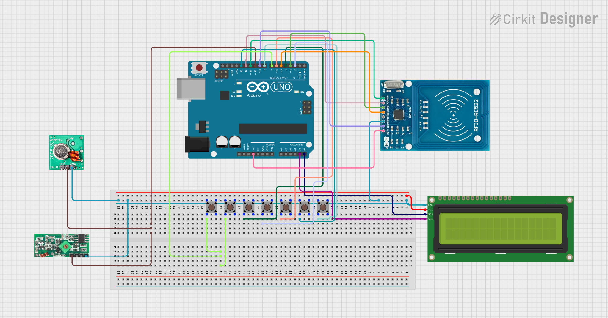
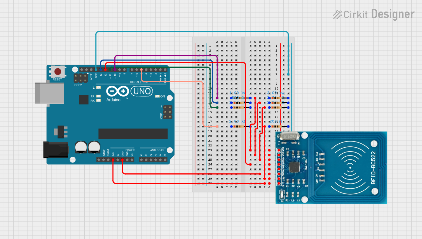
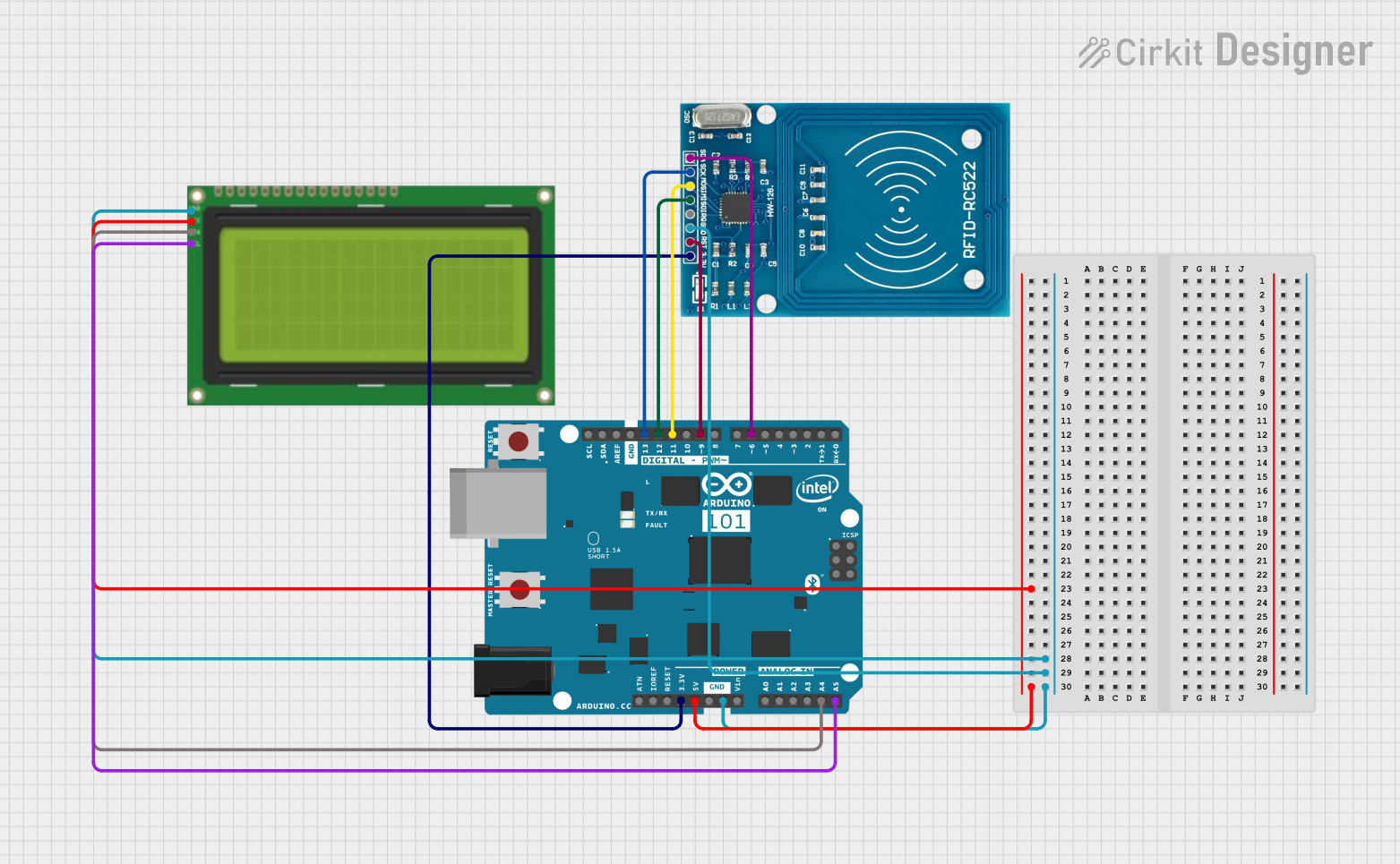

Explore Projects Built with RFID Reader
Technical Specifications
Below are the general technical specifications for a typical RFID Reader. Note that specific models may vary slightly in their specifications.
General Specifications
- Operating Frequency: 125 kHz (Low Frequency), 13.56 MHz (High Frequency), or UHF (860–960 MHz)
- Communication Interface: UART, SPI, I2C, or USB
- Operating Voltage: 3.3V or 5V (depending on the model)
- Current Consumption: Typically 50–100 mA
- Reading Range: 2 cm to 10 cm (varies by tag and reader type)
- Supported Protocols: ISO/IEC 14443A/B, ISO/IEC 15693, EPC Gen2, etc.
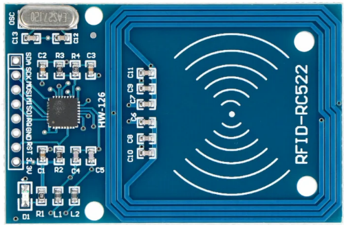
Pin Configuration
The pin configuration for a common RFID Reader module (e.g., RC522) is as follows:
| Pin Name | Description |
|---|---|
| VCC | Power supply input (3.3V or 5V) |
| GND | Ground |
| RST | Reset pin (active low) |
| IRQ | Interrupt request (optional) |
| MISO/SCL | Master-In-Slave-Out (SPI) or Clock |
| MOSI/SDA | Master-Out-Slave-In (SPI) or Data |
| SCK | Serial Clock (SPI) |
| NSS/CS | Chip Select (SPI) |
Usage Instructions
How to Use the RFID Reader in a Circuit
- Power the Module: Connect the VCC pin to a 3.3V or 5V power source (as per the module's requirements) and the GND pin to the ground.
- Connect Communication Pins: Depending on the communication protocol (e.g., SPI, I2C, or UART), connect the corresponding pins (e.g., MOSI, MISO, SCK, and NSS for SPI) to your microcontroller or host system.
- Place the RFID Tag: Position the RFID tag within the reader's range (typically 2–10 cm).
- Read Data: Use the appropriate software library or firmware to initialize the reader and retrieve data from the tag.
Important Considerations and Best Practices
- Ensure the RFID Reader operates at the correct voltage level to avoid damage.
- Avoid placing metallic objects near the reader, as they can interfere with radio frequency signals.
- Use decoupling capacitors near the power pins to reduce noise and ensure stable operation.
- If using SPI communication, ensure the microcontroller's SPI clock speed is compatible with the RFID Reader.
Example Code for Arduino UNO
Below is an example of how to use the RC522 RFID Reader with an Arduino UNO. This code uses the popular MFRC522 library.
#include <SPI.h>
#include <MFRC522.h>

// Define RFID Reader pins
#define RST_PIN 9  // Reset pin connected to Arduino pin 9
#define SS_PIN 10  // Slave Select pin connected to Arduino pin 10

MFRC522 rfid(SS_PIN, RST_PIN); // Create an instance of the RFID reader

void setup() {
  Serial.begin(9600); // Initialize serial communication
  SPI.begin();        // Initialize SPI bus
  rfid.PCD_Init();    // Initialize the RFID reader
  Serial.println("Place an RFID tag near the reader...");
}

void loop() {
  // Check if an RFID tag is present
  if (!rfid.PICC_IsNewCardPresent() || !rfid.PICC_ReadCardSerial()) {
    return; // Exit if no tag is detected
  }

  // Print the UID (Unique Identifier) of the tag
  Serial.print("Tag UID: ");
  for (byte i = 0; i < rfid.uid.size; i++) {
    Serial.print(rfid.uid.uidByte[i], HEX); // Print each byte in hexadecimal
    Serial.print(" ");
  }
  Serial.println();

  // Halt the tag to stop further communication
  rfid.PICC_HaltA();
}
Notes:
- Install the
MFRC522library in the Arduino IDE before uploading the code. - Ensure the wiring matches the pin definitions in the code.
Troubleshooting and FAQs
Common Issues
RFID Reader Not Powering On
- Solution: Verify the power supply voltage and connections. Ensure the VCC and GND pins are properly connected.
Unable to Read RFID Tags
- Solution: Check the tag's compatibility with the reader (e.g., frequency and protocol). Ensure the tag is within the reader's range.
Interference or Unstable Readings
- Solution: Remove any metallic objects near the reader. Use proper shielding if necessary.
Communication Errors with Microcontroller
- Solution: Double-check the wiring and pin assignments. Ensure the communication protocol (e.g., SPI) is correctly configured in the code.
FAQs
Q: Can the RFID Reader write data to tags?
- A: Some RFID Readers, such as the RC522, support writing data to compatible tags. Refer to the module's datasheet for details.
Q: What is the maximum range of an RFID Reader?
- A: The range depends on the reader and tag type. Typical ranges are 2–10 cm for low-power modules.
Q: Can multiple RFID Readers operate in the same area?
- A: Yes, but ensure they operate on different frequencies or use proper synchronization to avoid interference.
By following this documentation, you can effectively integrate and troubleshoot an RFID Reader in your projects.