
How to Use LIS2DW12 Breakout: Examples, Pinouts, and Specs
 Design with LIS2DW12 Breakout in Cirkit Designer
Introduction
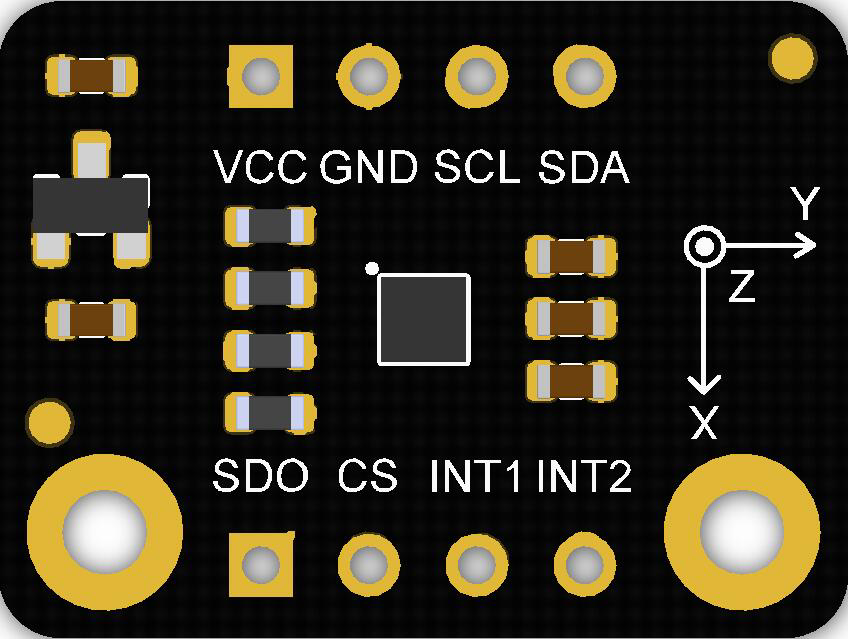
The LIS2DW12 Breakout (Manufacturer Part ID: SEN0405) by DFRobot is a compact and versatile accelerometer sensor module. It features the LIS2DW12 sensor, which is capable of measuring acceleration in three axes (X, Y, Z). This breakout board is designed for ease of use, with onboard connections for power and data communication, making it an excellent choice for prototyping and integration into various electronic projects.
Explore Projects Built with LIS2DW12 Breakout
 Open Project in Cirkit Designer
 Open Project in Cirkit Designer
 Open Project in Cirkit Designer
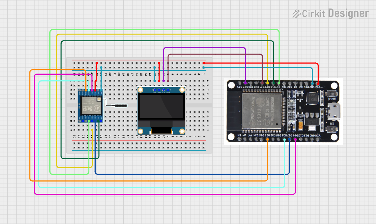 Open Project in Cirkit Designer
Explore Projects Built with LIS2DW12 Breakout
Open Project in Cirkit DesignerOpen Project in Cirkit DesignerOpen Project in Cirkit DesignerOpen Project in Cirkit DesignerCommon Applications
- Motion detection and gesture recognition
- Tilt sensing and orientation tracking
- Vibration monitoring
- Wearable devices
- Robotics and automation systems
Technical Specifications
The LIS2DW12 Breakout is built around the LIS2DW12 accelerometer sensor, which offers high performance and low power consumption. Below are the key technical details:
Key Specifications
| Parameter | Value |
|---|---|
| Operating Voltage | 3.3V to 5V |
| Communication Interface | I2C, SPI |
| Measurement Range | ±2g, ±4g, ±8g, ±16g (configurable) |
| Output Data Rate (ODR) | 1.6 Hz to 1.6 kHz |
| Power Consumption | 50 nA in low-power mode |
| Operating Temperature | -40°C to +85°C |
| Dimensions | 22mm x 22mm |
Pin Configuration
The breakout board includes the following pins for power and communication:
| Pin Name | Description |
|---|---|
| VIN | Power input (3.3V to 5V) |
| GND | Ground |
| SDA | I2C data line |
| SCL | I2C clock line |
| CS | Chip select for SPI communication |
| SDO/SA0 | SPI data out / I2C address selection |
| INT1 | Interrupt 1 output |
| INT2 | Interrupt 2 output |
Usage Instructions
The LIS2DW12 Breakout can be easily integrated into your project using either the I2C or SPI communication protocol. Below are the steps to get started:
Connecting the Breakout to an Arduino UNO
Wiring:
- Connect the VIN pin to the 5V pin on the Arduino.
- Connect the GND pin to the GND pin on the Arduino.
- Connect the SDA pin to the A4 pin on the Arduino (I2C data line).
- Connect the SCL pin to the A5 pin on the Arduino (I2C clock line).
Install Required Libraries:
- Download and install the
DFRobot_LIS2DW12library from the Arduino Library Manager.
- Download and install the
Example Code: Use the following example code to read acceleration data from the LIS2DW12 sensor:
#include <Wire.h>
#include "DFRobot_LIS2DW12.h"

// Create an instance of the LIS2DW12 sensor
DFRobot_LIS2DW12 lis;

void setup() {
  Serial.begin(9600); // Initialize serial communication
  while (!Serial);

  // Initialize the sensor
  if (!lis.begin()) {
    Serial.println("Failed to initialize LIS2DW12 sensor!");
    while (1);
  }

  // Configure the sensor
  lis.setRange(DFRobot_LIS2DW12::e4_g); // Set range to ±4g
  lis.setDataRate(DFRobot_LIS2DW12::eRate_100hz); // Set data rate to 100 Hz
  Serial.println("LIS2DW12 initialized successfully!");
}

void loop() {
  // Read acceleration data
  float x = lis.readAccX(); // Acceleration in X-axis (g)
  float y = lis.readAccY(); // Acceleration in Y-axis (g)
  float z = lis.readAccZ(); // Acceleration in Z-axis (g)

  // Print the data to the Serial Monitor
  Serial.print("X: ");
  Serial.print(x, 2); // Print X-axis data with 2 decimal places
  Serial.print(" g, Y: ");
  Serial.print(y, 2); // Print Y-axis data with 2 decimal places
  Serial.print(" g, Z: ");
  Serial.print(z, 2); // Print Z-axis data with 2 decimal places
  Serial.println(" g");

  delay(100); // Delay for 100 ms
}
Important Considerations
- Ensure the I2C address of the sensor matches the default address (0x19). If using multiple sensors, adjust the address using the SDO/SA0 pin.
- Use appropriate pull-up resistors (typically 4.7kΩ) on the SDA and SCL lines if not already included on the breakout board.
- Avoid exposing the sensor to extreme temperatures or mechanical shocks beyond its rated limits.
Troubleshooting and FAQs
Common Issues
Sensor Not Detected:
- Ensure the wiring is correct and matches the pin configuration.
- Verify that the I2C address is correct (default: 0x19).
- Check for loose connections or damaged wires.
Incorrect or No Data Output:
- Confirm that the sensor is properly initialized in the code.
- Ensure the correct range and data rate are configured.
- Check the power supply voltage (3.3V to 5V).
Intermittent Communication Failures:
- Use shorter wires to reduce noise in the I2C or SPI lines.
- Add pull-up resistors to the SDA and SCL lines if necessary.
FAQs
Q: Can I use the LIS2DW12 Breakout with a 3.3V microcontroller?
A: Yes, the breakout board supports both 3.3V and 5V logic levels, making it compatible with a wide range of microcontrollers.
Q: How do I change the I2C address of the sensor?
A: The I2C address can be changed by connecting the SDO/SA0 pin to either GND (0x18) or VIN (0x19).
Q: What is the maximum sampling rate of the LIS2DW12 sensor?
A: The sensor supports output data rates (ODR) up to 1.6 kHz.
Q: Can I use the LIS2DW12 Breakout for vibration monitoring?
A: Yes, the sensor's high sensitivity and configurable range make it suitable for vibration monitoring applications.
By following this documentation, you can effectively integrate the LIS2DW12 Breakout into your projects and troubleshoot any issues that arise.