How to Use Battey Indicator: Examples, Pinouts, and Specs
Introduction
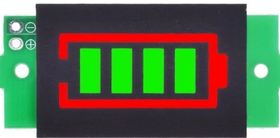
A Battery Indicator is an electronic device designed to display the charge level of a battery. It typically uses a series of LEDs, an LCD, or a gauge to visually indicate whether the battery is full, half-charged, or low. This component is widely used in portable electronics, electric vehicles, power banks, and renewable energy systems to monitor battery health and prevent over-discharge or overcharging.
Explore Projects Built with Battey Indicator
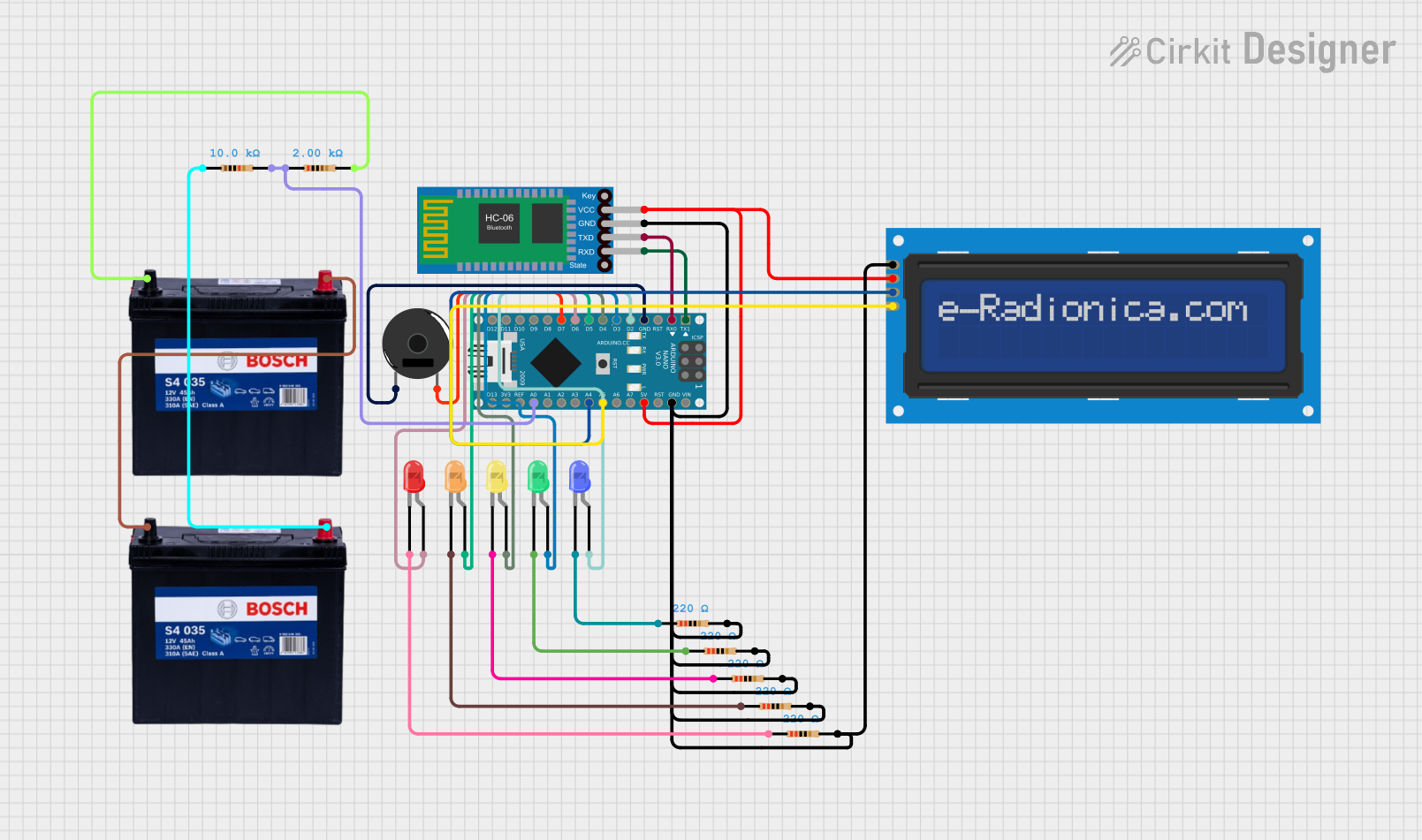


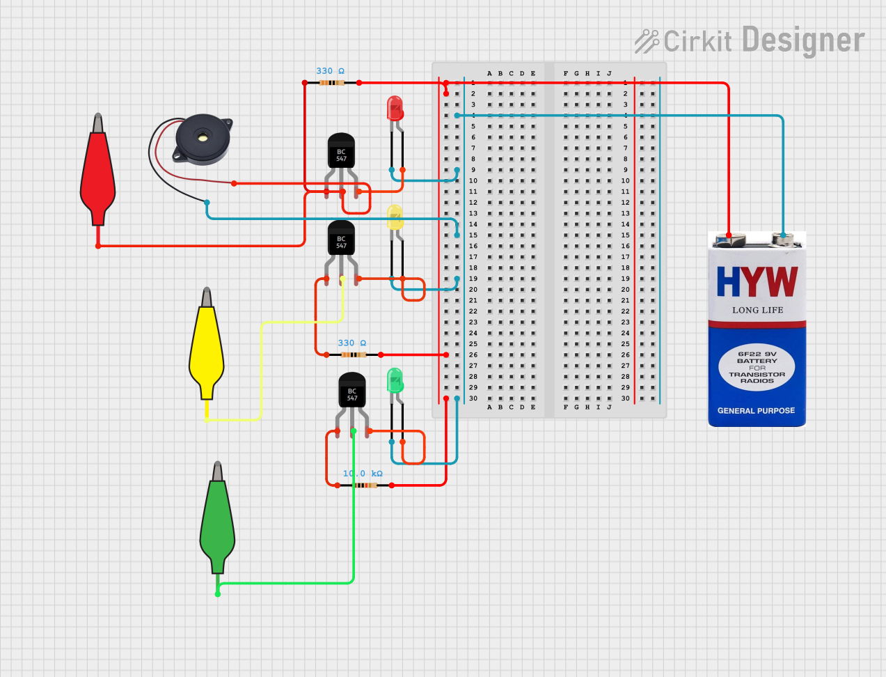
Explore Projects Built with Battey Indicator
Common Applications and Use Cases
- Portable electronic devices (e.g., smartphones, laptops, power banks)
- Electric vehicles and scooters
- Solar power systems
- Uninterruptible Power Supplies (UPS)
- Battery-powered tools and appliances
Technical Specifications
Below are the general technical specifications for a typical Battery Indicator module. Specifications may vary depending on the specific model or manufacturer.
| Parameter | Value |
|---|---|
| Operating Voltage | 3.7V to 24V (varies by model) |
| Operating Current | 10mA to 50mA |
| Display Type | LED bar, LCD, or analog gauge |
| Battery Type Supported | Lithium-ion, Lead-acid, NiMH, etc. |
| Number of Indicators | 3 to 10 LEDs or equivalent levels |
| Accuracy | ±5% |
| Operating Temperature | -20°C to 70°C |
Pin Configuration and Descriptions
The pinout for a typical Battery Indicator module is as follows:
| Pin Name | Description |
|---|---|
| VCC | Positive power supply input (connect to battery positive terminal) |
| GND | Ground connection (connect to battery negative terminal) |
| BAT+ | Battery positive terminal input (used for voltage sensing) |
| BAT- | Battery negative terminal input (used for voltage sensing) |
| OUT | Optional output pin for connecting to external circuits (e.g., alarms, relays) |
Usage Instructions
How to Use the Component in a Circuit
- Power Connection: Connect the
VCCpin to the positive terminal of the battery and theGNDpin to the negative terminal. - Voltage Sensing: Connect the
BAT+andBAT-pins to the corresponding battery terminals. This allows the module to measure the battery voltage. - Display: The indicator will automatically light up LEDs or update the display to show the battery's charge level.
- Optional Output: If the module has an
OUTpin, it can be used to trigger external devices (e.g., a buzzer for low battery warnings).
Important Considerations and Best Practices
- Voltage Range: Ensure the module's operating voltage matches the battery's voltage range. Using a module outside its specified range may damage the component or provide inaccurate readings.
- Battery Type: Verify that the indicator is compatible with the type of battery being used (e.g., lithium-ion, lead-acid).
- Polarity: Double-check the polarity of all connections to avoid damaging the module or the battery.
- Calibration: Some modules may require calibration to accurately display charge levels. Refer to the manufacturer's instructions for details.
- Arduino Integration: Many Battery Indicators can be interfaced with microcontrollers like the Arduino UNO for advanced monitoring and control.
Example Arduino Code
Below is an example of how to interface a Battery Indicator with an Arduino UNO to monitor battery voltage:
// Define the analog pin connected to the BAT+ pin of the Battery Indicator
const int batteryPin = A0;

// Define the reference voltage of the Arduino (typically 5V or 3.3V)
const float referenceVoltage = 5.0;

// Define the maximum battery voltage (e.g., 12V for a 12V battery)
const float maxBatteryVoltage = 12.0;

void setup() {
  Serial.begin(9600); // Initialize serial communication for debugging
}

void loop() {
  // Read the analog value from the battery pin
  int analogValue = analogRead(batteryPin);

  // Convert the analog value to a voltage
  float batteryVoltage = (analogValue / 1023.0) * referenceVoltage * (maxBatteryVoltage / referenceVoltage);

  // Print the battery voltage to the Serial Monitor
  Serial.print("Battery Voltage: ");
  Serial.print(batteryVoltage);
  Serial.println("V");

  // Add a delay to avoid flooding the Serial Monitor
  delay(1000);
}
Note: Use a voltage divider circuit if the battery voltage exceeds the Arduino's input voltage range (e.g., 5V for most Arduino boards).
Troubleshooting and FAQs
Common Issues and Solutions
No Display or LEDs Not Lighting Up
- Cause: Incorrect wiring or insufficient power supply.
- Solution: Verify all connections and ensure the battery voltage is within the module's operating range.
Inaccurate Battery Level Indication
- Cause: Module not calibrated for the specific battery type.
- Solution: Check the manufacturer's instructions for calibration procedures.
Module Overheating
- Cause: Exceeding the module's voltage or current limits.
- Solution: Ensure the battery voltage and current are within the specified range.
Output Pin Not Triggering External Devices
- Cause: Incorrect configuration or insufficient load.
- Solution: Verify the output pin's voltage and current ratings and ensure the connected device is compatible.
FAQs
Q: Can I use a Battery Indicator with a rechargeable battery?
A: Yes, most Battery Indicators are designed to work with rechargeable batteries, such as lithium-ion or lead-acid batteries. Ensure compatibility with the specific battery type.
Q: How do I know if the battery is fully charged?
A: When the battery is fully charged, all LEDs on the indicator will light up, or the display will show the maximum charge level.
Q: Can I use the Battery Indicator with an Arduino for advanced monitoring?
A: Yes, you can connect the indicator to an Arduino to read battery voltage and implement custom monitoring or control features.
Q: What happens if I connect the module with reversed polarity?
A: Reversing the polarity may damage the module. Always double-check connections before powering the circuit.
Q: Is the Battery Indicator waterproof?
A: Most Battery Indicators are not waterproof. If you need to use the module in a wet environment, consider using a waterproof enclosure.