How to Use BTS 7960 Dual Channel DC Motor Drive Module H Bridge Motor Driver Board Speed Controller: Examples, Pinouts, and Specs
Introduction
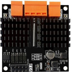
The BTS 7960 is a high-power dual-channel H-Bridge motor driver module designed for controlling DC motors. It is equipped with two BTS 7960 half-bridge driver ICs, which provide high current handling capability and efficient motor control. This module is ideal for applications requiring bidirectional motor control, such as robotics, electric vehicles, conveyor systems, and other motorized projects.
The BTS 7960 module supports PWM (Pulse Width Modulation) for speed control and features built-in protection mechanisms, including overcurrent, overtemperature, and short-circuit protection, ensuring reliable operation in demanding environments.
Explore Projects Built with BTS 7960 Dual Channel DC Motor Drive Module H Bridge Motor Driver Board Speed Controller

Explore Projects Built with BTS 7960 Dual Channel DC Motor Drive Module H Bridge Motor Driver Board Speed Controller
Technical Specifications
- Operating Voltage: 6V to 27V DC
- Maximum Continuous Current: 43A per channel
- Peak Current: 100A (short duration)
- PWM Frequency: Up to 25kHz
- Logic Voltage: 3.3V or 5V (compatible with most microcontrollers)
- Control Mode: PWM for speed control, logic signals for direction control
- Protection Features: Overcurrent, overtemperature, and short-circuit protection
- Dimensions: Approximately 43mm x 45mm
Pin Configuration and Descriptions
The BTS 7960 module has the following pin layout:
| Pin Name | Type | Description |
|---|---|---|
| VCC | Power Input | Connect to the motor power supply (6V to 27V DC). |
| GND | Power Ground | Ground connection for the motor power supply. |
| R_EN | Logic Input | Enable signal for the right motor channel. Active HIGH. |
| L_EN | Logic Input | Enable signal for the left motor channel. Active HIGH. |
| R_PWM | PWM Input | PWM signal for controlling the speed of the right motor channel. |
| L_PWM | PWM Input | PWM signal for controlling the speed of the left motor channel. |
| R_IS | Analog Output | Current sense output for the right motor channel. |
| L_IS | Analog Output | Current sense output for the left motor channel. |
| RPWM | Logic Input | Direction control signal for the right motor channel. |
| LPWM | Logic Input | Direction control signal for the left motor channel. |
Usage Instructions
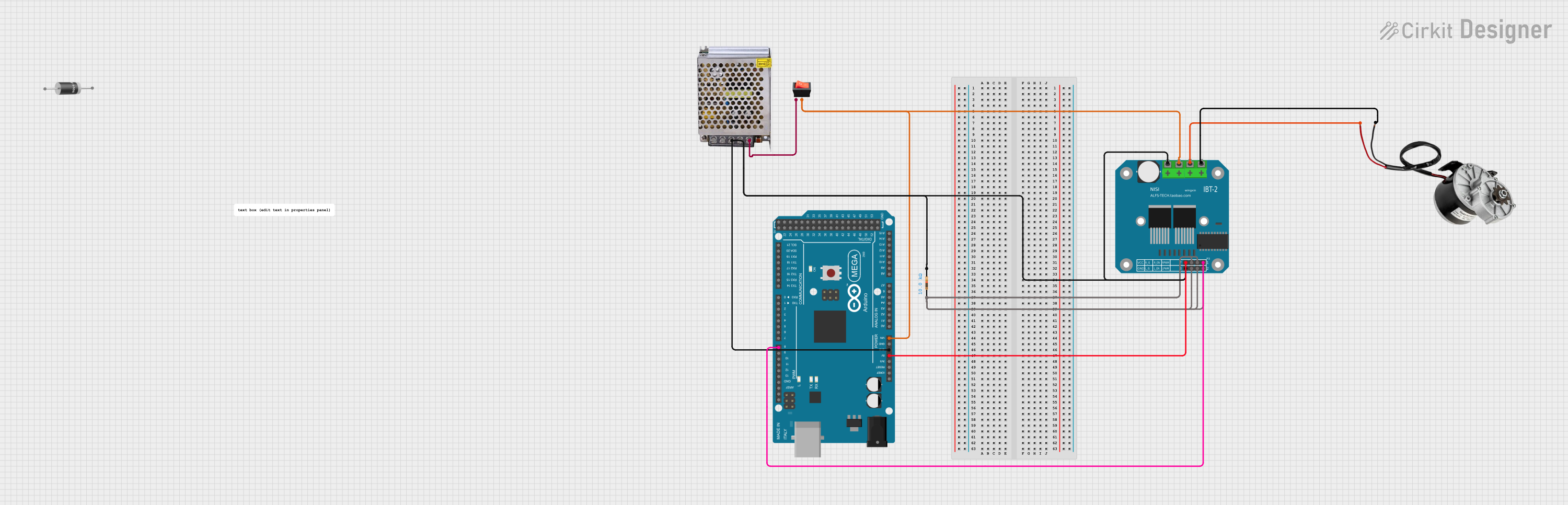
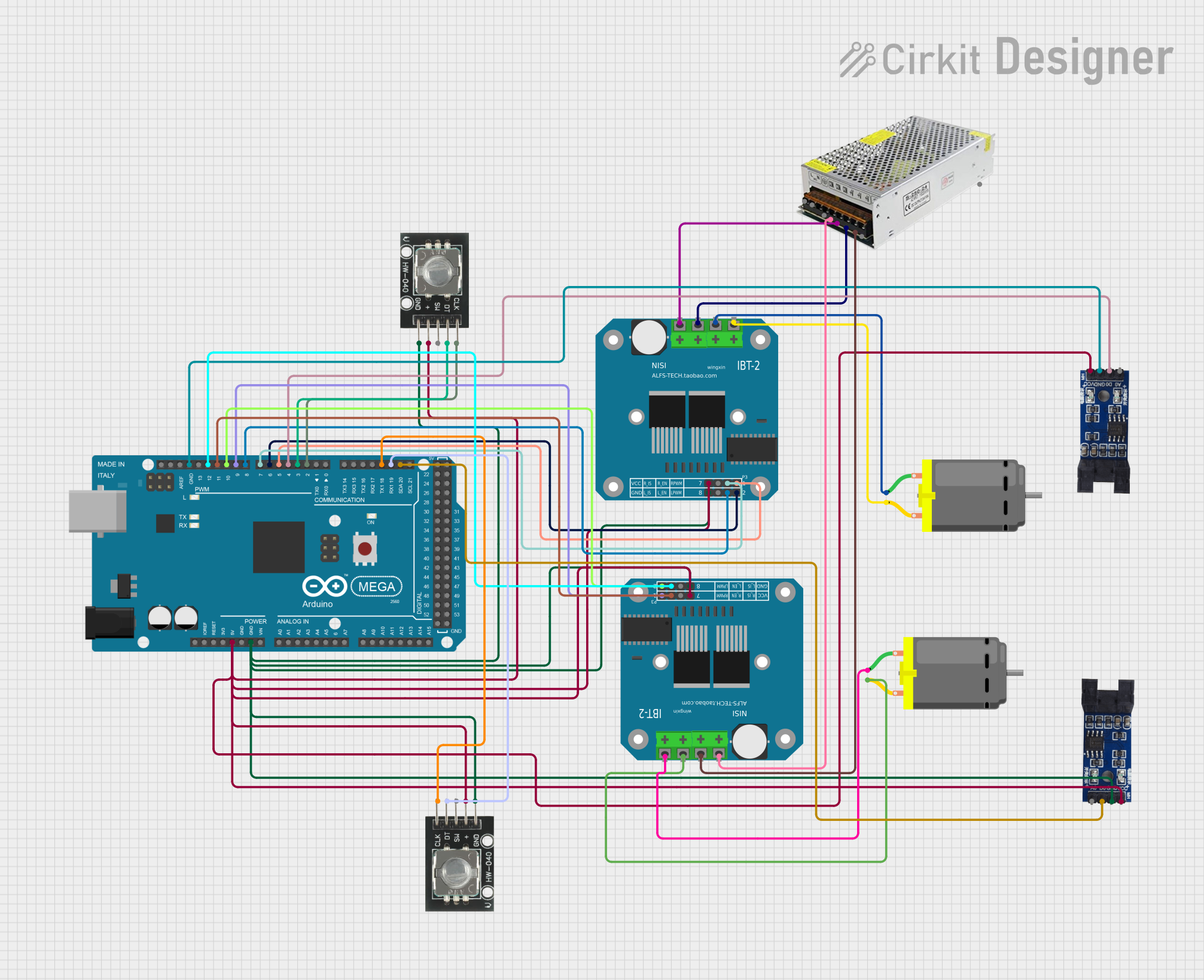
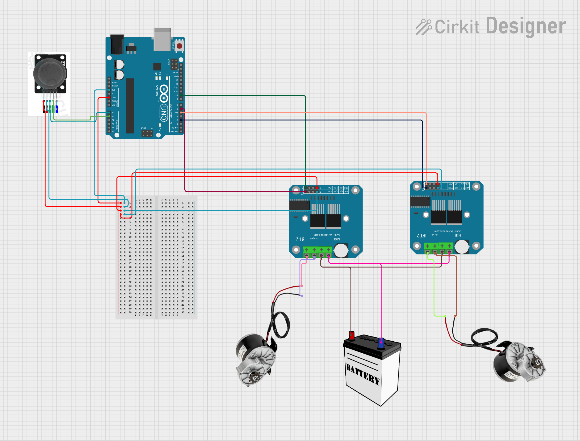
Connecting the BTS 7960 to a Circuit
- Power Supply: Connect the VCC pin to the positive terminal of the motor power supply (6V to 27V DC) and the GND pin to the ground terminal.
- Motor Connections: Connect the motor terminals to the output terminals of the module.
- Logic Connections:
- Connect the R_EN and L_EN pins to the microcontroller's GPIO pins to enable the respective motor channels.
- Use the R_PWM and L_PWM pins to send PWM signals for speed control.
- Connect the RPWM and LPWM pins to control the motor's direction.
- Microcontroller Logic Voltage: Ensure the logic voltage level (3.3V or 5V) matches the microcontroller's output.
Example Code for Arduino UNO
Below is an example of how to control a DC motor using the BTS 7960 module with an Arduino UNO:
// Define pins for the BTS 7960 module
#define R_EN 7    // Right channel enable pin
#define L_EN 8    // Left channel enable pin
#define R_PWM 9   // Right channel PWM pin
#define L_PWM 10  // Left channel PWM pin
#define RPWM 11   // Right channel direction pin
#define LPWM 12   // Left channel direction pin

void setup() {
  // Set pin modes
  pinMode(R_EN, OUTPUT);
  pinMode(L_EN, OUTPUT);
  pinMode(R_PWM, OUTPUT);
  pinMode(L_PWM, OUTPUT);
  pinMode(RPWM, OUTPUT);
  pinMode(LPWM, OUTPUT);

  // Enable both motor channels
  digitalWrite(R_EN, HIGH);
  digitalWrite(L_EN, HIGH);
}

void loop() {
  // Example: Rotate motor forward at 50% speed
  analogWrite(R_PWM, 128);  // Set right motor speed (0-255)
  digitalWrite(RPWM, HIGH); // Set right motor direction forward
  digitalWrite(LPWM, LOW);  // Ensure left motor direction is off

  delay(2000); // Run motor for 2 seconds

  // Example: Rotate motor backward at 75% speed
  analogWrite(R_PWM, 192);  // Set right motor speed (0-255)
  digitalWrite(RPWM, LOW);  // Set right motor direction backward
  digitalWrite(LPWM, HIGH); // Ensure left motor direction is off

  delay(2000); // Run motor for 2 seconds
}
Important Considerations
- Ensure the motor's current and voltage ratings are within the module's specifications.
- Use appropriate heat dissipation methods (e.g., heatsinks) if operating at high currents for extended periods.
- Avoid reversing the power supply polarity to prevent damage to the module.
- Use a separate power supply for the motor and the microcontroller to avoid noise interference.
Troubleshooting and FAQs
Common Issues
Motor Not Running:
- Verify that the VCC and GND connections are secure and the power supply is within the specified range.
- Check that the R_EN and L_EN pins are set HIGH to enable the motor channels.
- Ensure the PWM signal is being sent correctly to the R_PWM or L_PWM pins.
Motor Running in the Wrong Direction:
- Verify the logic levels on the RPWM and LPWM pins. Swap the HIGH/LOW signals if necessary.
Overheating:
- Ensure the module is not exceeding its current rating. Use a heatsink or fan if needed.
- Check for short circuits in the motor wiring.
No Response to PWM Signals:
- Confirm that the PWM frequency is within the module's supported range (up to 25kHz).
- Ensure the microcontroller's logic voltage matches the module's requirements.
FAQs
Q: Can I use the BTS 7960 module with a 3.3V microcontroller?
A: Yes, the module is compatible with both 3.3V and 5V logic levels.
Q: What is the maximum motor power I can control with this module?
A: The module can handle up to 43A continuous current per channel, with a peak current of 100A for short durations. Ensure the motor's power requirements are within these limits.
Q: How do I protect the module from damage?
A: Use appropriate fuses and ensure proper wiring. Avoid exceeding the voltage and current ratings, and use heatsinks for high-power applications.
Q: Can I control two motors independently with this module?
A: No, the BTS 7960 module is designed to control a single motor with dual-channel H-Bridge functionality. For independent control of two motors, use two separate modules.