How to Use Adafruit EMC2101: Examples, Pinouts, and Specs
Introduction
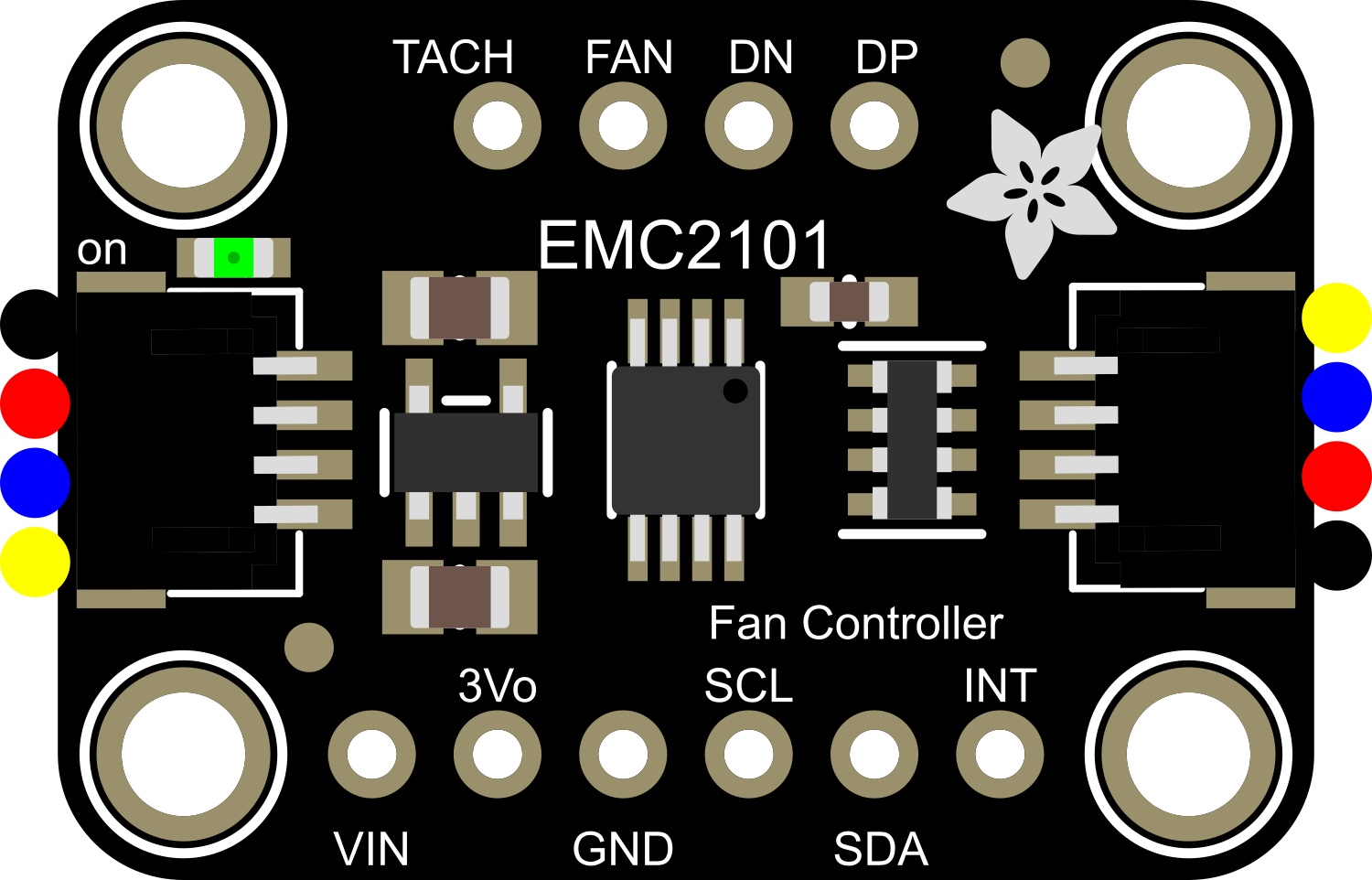
The Adafruit EMC2101 is an integrated temperature sensor and fan controller breakout board designed for efficient thermal management in electronic systems. Utilizing the EMC2101 chip, this board is capable of providing precise temperature measurements with an accuracy of ±1°C. It is ideal for applications that require active cooling, such as computer systems, gaming consoles, or any heat-sensitive electronics. The board's ability to control a fan based on temperature readings helps maintain optimal operating conditions, thereby enhancing the performance and longevity of the system.
Explore Projects Built with Adafruit EMC2101

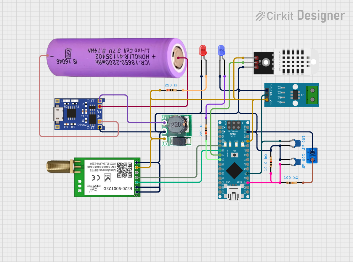
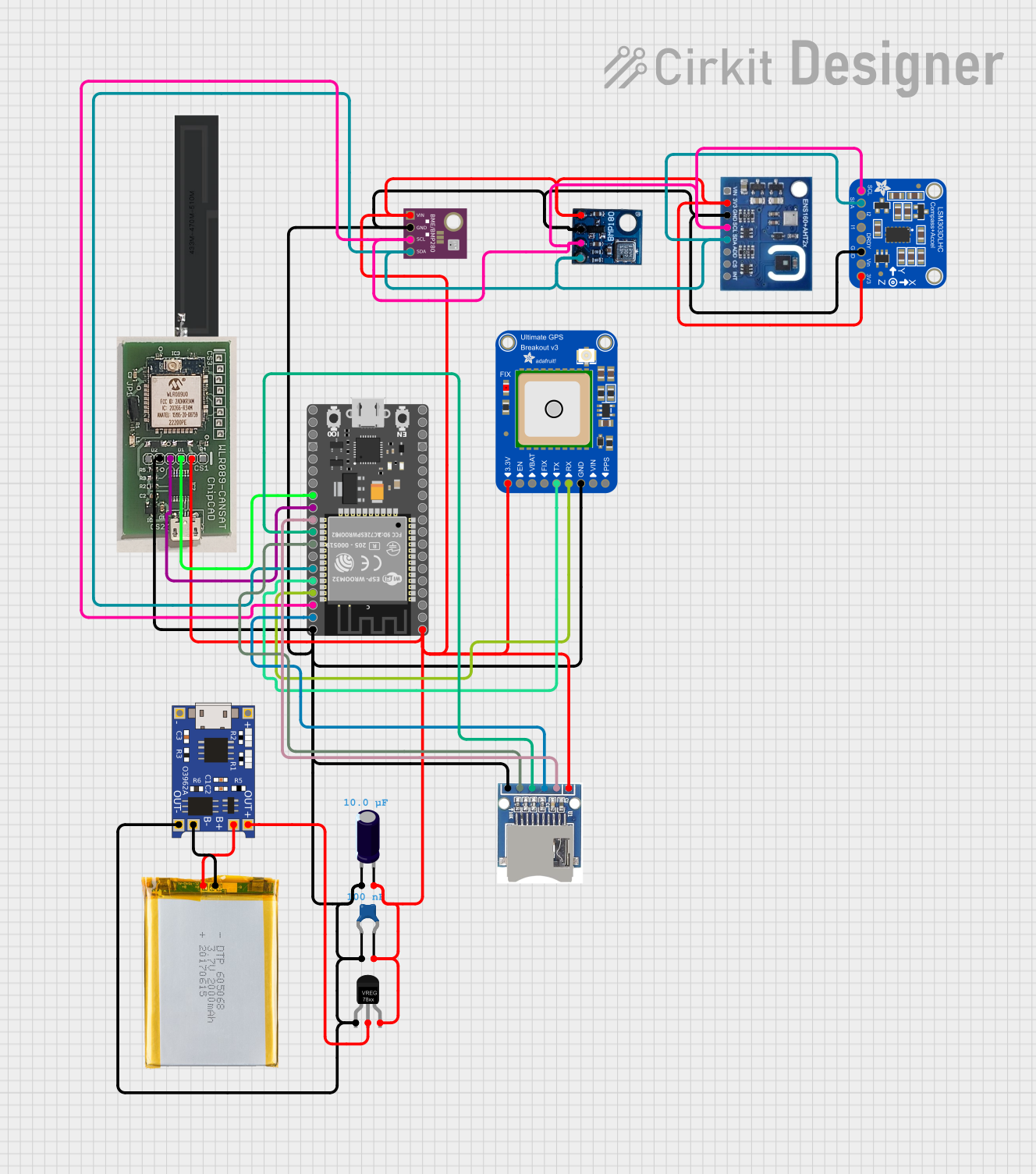
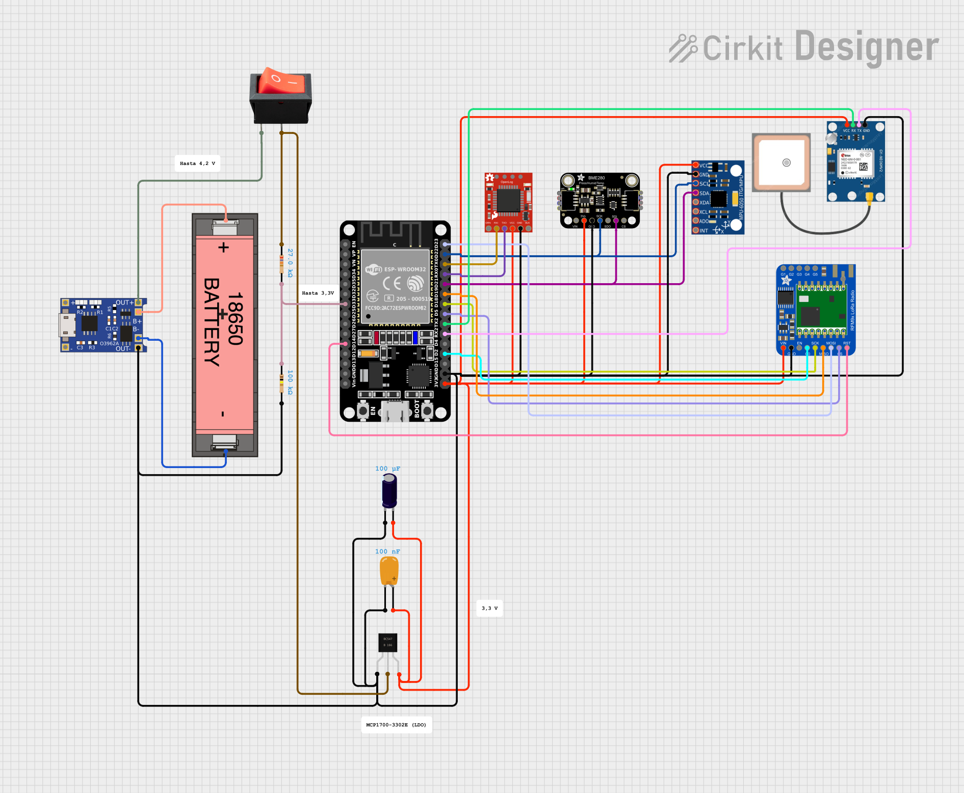
Explore Projects Built with Adafruit EMC2101
Common Applications and Use Cases
- Personal computer and server cooling systems
- Gaming consoles and VR hardware
- Overclocked systems requiring precise thermal management
- Industrial control systems with thermal regulation needs
- Robotics and automated systems with active cooling requirements
Technical Specifications
Key Technical Details
- Temperature Measurement Accuracy: ±1°C
- Operating Voltage: 3.3V to 5V
- Fan Control: PWM output for fan speed control
- Communication Interface: I2C
- I2C Addresses: 0x4C (default), selectable with jumpers
Pin Configuration and Descriptions
| Pin Number | Name | Description |
|---|---|---|
| 1 | GND | Ground connection |
| 2 | VIN | Input voltage (3.3V to 5V) |
| 3 | SDA | I2C Data line |
| 4 | SCL | I2C Clock line |
| 5 | FAN | PWM fan control output |
| 6 | TACH | Fan tachometer input for RPM feedback |
Usage Instructions
How to Use the Component in a Circuit
Powering the Board:
- Connect the VIN pin to a 3.3V or 5V power supply.
- Connect the GND pin to the ground of the power supply.
Connecting to a Microcontroller:
- Connect the SDA and SCL pins to the corresponding I2C data and clock lines on your microcontroller.
Fan Connection:
- Connect your fan's PWM input to the FAN pin on the board.
- If your fan provides RPM feedback, connect its tachometer output to the TACH pin.
I2C Communication:
- Use the default I2C address (0x4C) or configure a different address using the onboard jumpers if necessary.
Important Considerations and Best Practices
- Ensure that the input voltage does not exceed the specified range to prevent damage to the board.
- When connecting a fan, verify that the fan's voltage and current ratings are compatible with the board's output.
- Use pull-up resistors on the I2C lines if your microcontroller does not have built-in pull-ups.
- Place the temperature sensor in a location that accurately represents the system's temperature for effective fan control.
Example Code for Arduino UNO
#include <Wire.h>

// EMC2101 I2C address
#define EMC2101_ADDRESS 0x4C

// Register addresses
#define TEMPERATURE_REGISTER 0x00
#define FAN_SPEED_REGISTER 0x10 // Example register for fan speed

void setup() {
  Wire.begin(); // Initialize I2C
  Serial.begin(9600); // Start serial communication
}

void loop() {
  int temperature = readTemperature();
  Serial.print("Temperature: ");
  Serial.print(temperature);
  Serial.println(" C");

  // Add your fan control logic here based on the temperature reading

  delay(1000); // Wait for 1 second before reading again
}

int readTemperature() {
  Wire.beginTransmission(EMC2101_ADDRESS);
  Wire.write(TEMPERATURE_REGISTER);
  Wire.endTransmission();
  Wire.requestFrom(EMC2101_ADDRESS, 1);

  if (Wire.available()) {
    return Wire.read(); // Read temperature value
  } else {
    return 0; // Return 0 if no data received
  }
}
Troubleshooting and FAQs
Common Issues Users Might Face
- Inaccurate Temperature Readings: Ensure that the sensor is not placed near heat-generating components unless intended for measuring their temperature.
- Fan Not Responding to PWM Signal: Check the fan specifications to ensure it supports PWM control and verify the connections.
- I2C Communication Errors: Confirm that the I2C address is correct and that there are no conflicts on the I2C bus.
Solutions and Tips for Troubleshooting
- If the temperature readings are consistently off, recalibrate the sensor or check for environmental factors affecting the sensor.
- For fan control issues, ensure that the PWM signal is within the fan's operating specifications.
- Use I2C scanning code to verify that the EMC2101 is detected on the I2C bus.
FAQs
Q: Can I connect multiple EMC2101 boards to a single microcontroller? A: Yes, you can connect multiple boards using different I2C addresses by configuring the onboard jumpers.
Q: What is the maximum fan current that the EMC2101 can handle? A: Refer to the EMC2101 datasheet for the maximum current rating for the fan controller output.
Q: How do I change the I2C address of the EMC2101? A: Adjust the address by changing the position of the jumpers on the board according to the datasheet instructions.
Q: Can the EMC2101 control more than one fan? A: The EMC2101 is designed to control a single fan. To control multiple fans, use additional EMC2101 boards or a fan hub that accepts a single PWM signal for multiple fans.