How to Use raspi schem: Examples, Pinouts, and Specs
Introduction
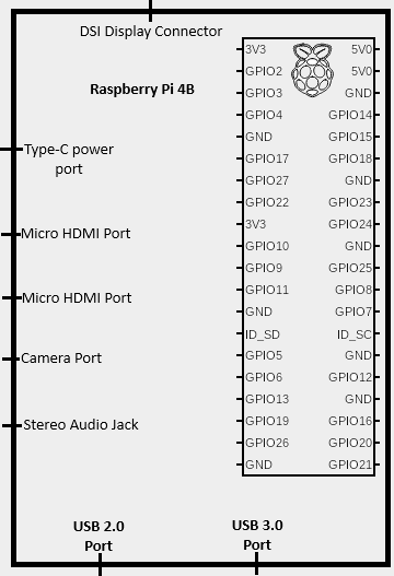
- The Raspi Schem is a schematic representation of the Raspberry Pi, designed to provide a detailed overview of its connections, GPIO pinouts, and interfacing options. It serves as a visual and technical guide for users looking to integrate the Raspberry Pi into their electronic projects.
- Common applications include prototyping, IoT development, robotics, home automation, and educational projects. The schematic is particularly useful for understanding how to connect sensors, actuators, and other peripherals to the Raspberry Pi.
Explore Projects Built with raspi schem
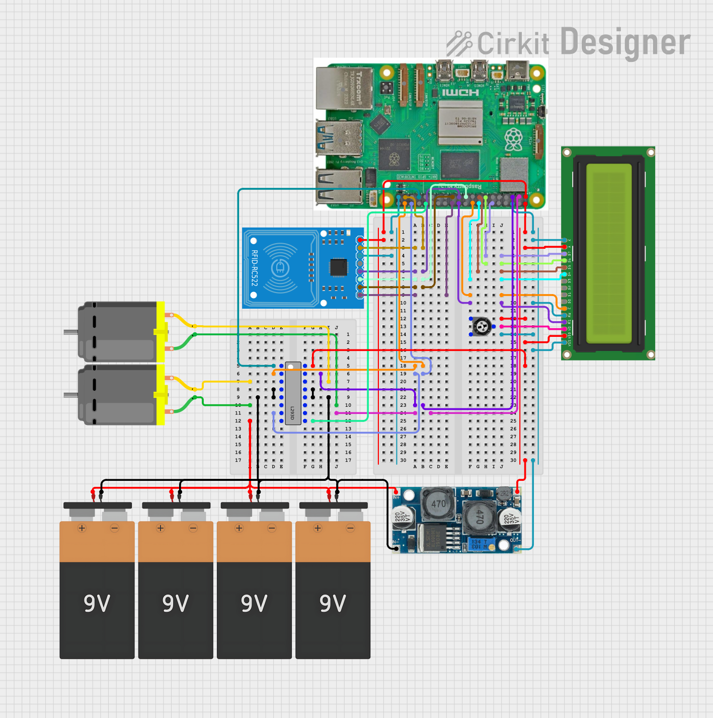
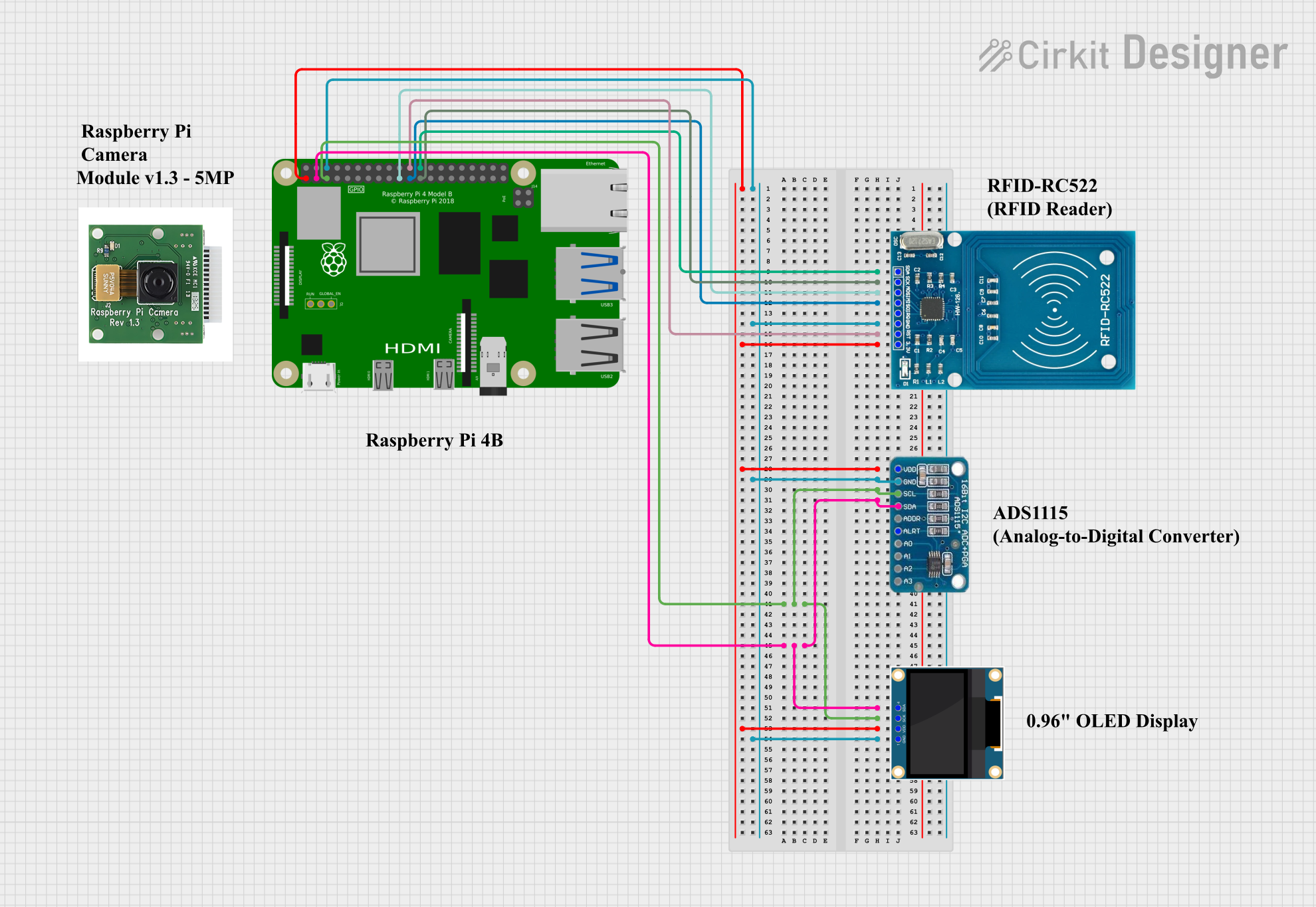
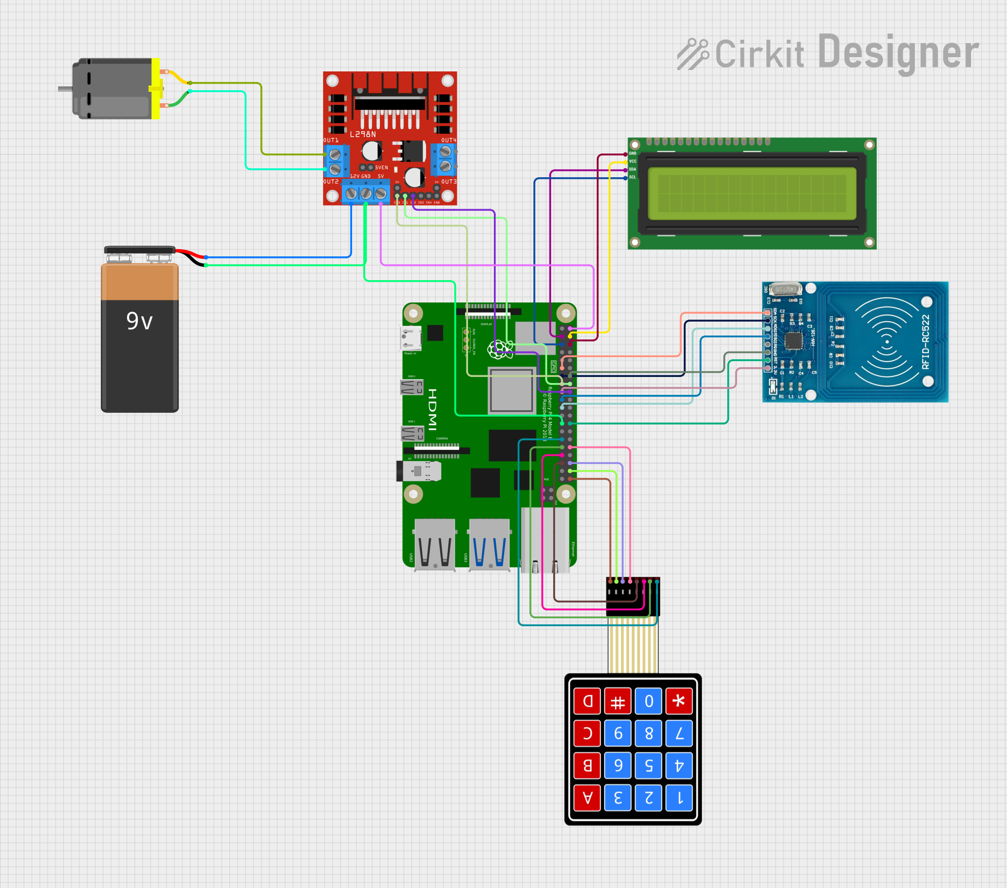
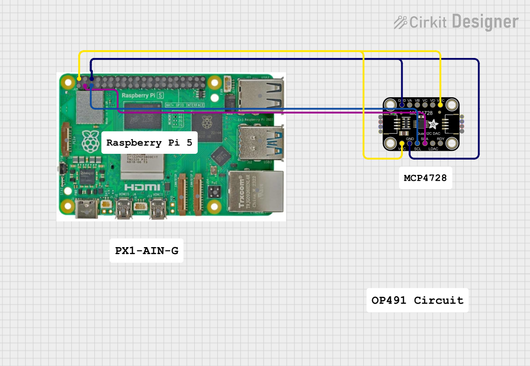
Explore Projects Built with raspi schem
Technical Specifications
- The Raspi Schem is based on the Raspberry Pi's 40-pin GPIO header and includes detailed labeling for power, ground, and data pins.
- It provides a clear representation of the following:
- GPIO pin numbering (BCM and physical layout)
- Power supply pins (3.3V and 5V)
- Ground pins
- Communication protocols (I2C, SPI, UART)
GPIO Pin Configuration
The Raspberry Pi's 40-pin GPIO header is represented in the schematic as follows:
| Pin Number (Physical) | Pin Name (BCM) | Functionality | Description |
|---|---|---|---|
| 1 | 3.3V | Power | 3.3V power supply |
| 2 | 5V | Power | 5V power supply |
| 3 | GPIO2 (SDA1) | I2C Data | Used for I2C communication |
| 4 | 5V | Power | 5V power supply |
| 5 | GPIO3 (SCL1) | I2C Clock | Used for I2C communication |
| 6 | GND | Ground | Ground connection |
| 7 | GPIO4 | General Purpose I/O | Configurable GPIO pin |
| 8 | GPIO14 (TXD) | UART Transmit | Serial communication (TX) |
| 9 | GND | Ground | Ground connection |
| 10 | GPIO15 (RXD) | UART Receive | Serial communication (RX) |
| ... | ... | ... | ... |
Note: The full 40-pin GPIO header is included in the schematic, but only a subset is shown here for brevity.
Usage Instructions
How to Use the Raspi Schem
- Understand the Pinout: Familiarize yourself with the GPIO pin numbering (both physical and BCM) using the schematic.
- Plan Your Connections: Use the schematic to identify the appropriate pins for power, ground, and data connections.
- Connect Components:
- For sensors and actuators, connect the data pins to the appropriate GPIO pins.
- Use the 3.3V or 5V pins to power external components, ensuring they do not exceed the Raspberry Pi's current limits.
- Always connect the ground (GND) pins to establish a common reference point.
- Use Pull-Up/Pull-Down Resistors: For GPIO pins configured as inputs, consider using pull-up or pull-down resistors to avoid floating states.
Example: Interfacing an LED with the Raspberry Pi
Below is an example of how to use the schematic to connect an LED to GPIO17 (physical pin 11) and control it using Python.
Circuit Setup
- Connect the anode (long leg) of the LED to GPIO17.
- Connect the cathode (short leg) of the LED to a 330-ohm resistor.
- Connect the other end of the resistor to GND.
Python Code
Import the GPIO library
import RPi.GPIO as GPIO import time
Set the GPIO mode to BCM (Broadcom pin numbering)
GPIO.setmode(GPIO.BCM)
Define the GPIO pin for the LED
LED_PIN = 17
Set up the LED pin as an output
GPIO.setup(LED_PIN, GPIO.OUT)
Blink the LED in a loop
try: while True: GPIO.output(LED_PIN, GPIO.HIGH) # Turn the LED on time.sleep(1) # Wait for 1 second GPIO.output(LED_PIN, GPIO.LOW) # Turn the LED off time.sleep(1) # Wait for 1 second except KeyboardInterrupt: # Clean up GPIO settings on exit GPIO.cleanup()
Best Practices
- Avoid exceeding the maximum current draw of the GPIO pins (16mA per pin, 50mA total).
- Use level shifters when interfacing with 5V logic devices.
- Double-check connections against the schematic to prevent short circuits or damage.
Troubleshooting and FAQs
Common Issues
Incorrect Pin Numbering:
- Problem: Confusion between physical and BCM pin numbering.
- Solution: Refer to the schematic to ensure the correct pin numbering is used.
Overloading GPIO Pins:
- Problem: Drawing too much current from a GPIO pin, causing the Raspberry Pi to malfunction.
- Solution: Use external power sources for high-current devices and limit GPIO current to 16mA per pin.
Floating GPIO Pins:
- Problem: GPIO pins configured as inputs may pick up noise if left unconnected.
- Solution: Use pull-up or pull-down resistors to stabilize the input state.
No Response from Connected Devices:
- Problem: Incorrect wiring or misconfigured GPIO settings.
- Solution: Double-check connections and ensure the GPIO pins are correctly configured in your code.
FAQs
Q: Can I use the 5V pins to power external devices?
- A: Yes, but ensure the total current draw does not exceed the Raspberry Pi's power supply capacity.
Q: How do I identify the BCM pin numbers on the schematic?
- A: The schematic includes both physical and BCM pin numbers for easy reference.
Q: What precautions should I take when connecting sensors?
- A: Verify the voltage and current requirements of the sensor and use level shifters if necessary.
By following the Raspi Schem, you can confidently design and implement projects with the Raspberry Pi, ensuring proper connections and functionality.