How to Use EasyDriver_v45: Examples, Pinouts, and Specs
Introduction
The EasyDriver v4.5 is a compact and versatile stepper motor driver board that simplifies the process of controlling bipolar stepper motors for hobbyists and professionals alike. It is based on the Allegro A4988 stepper driver chip, which is renowned for its performance and reliability. The EasyDriver v4.5 is commonly used in CNC machines, 3D printers, robotics, and other applications where precise motor control is required.
Explore Projects Built with EasyDriver_v45
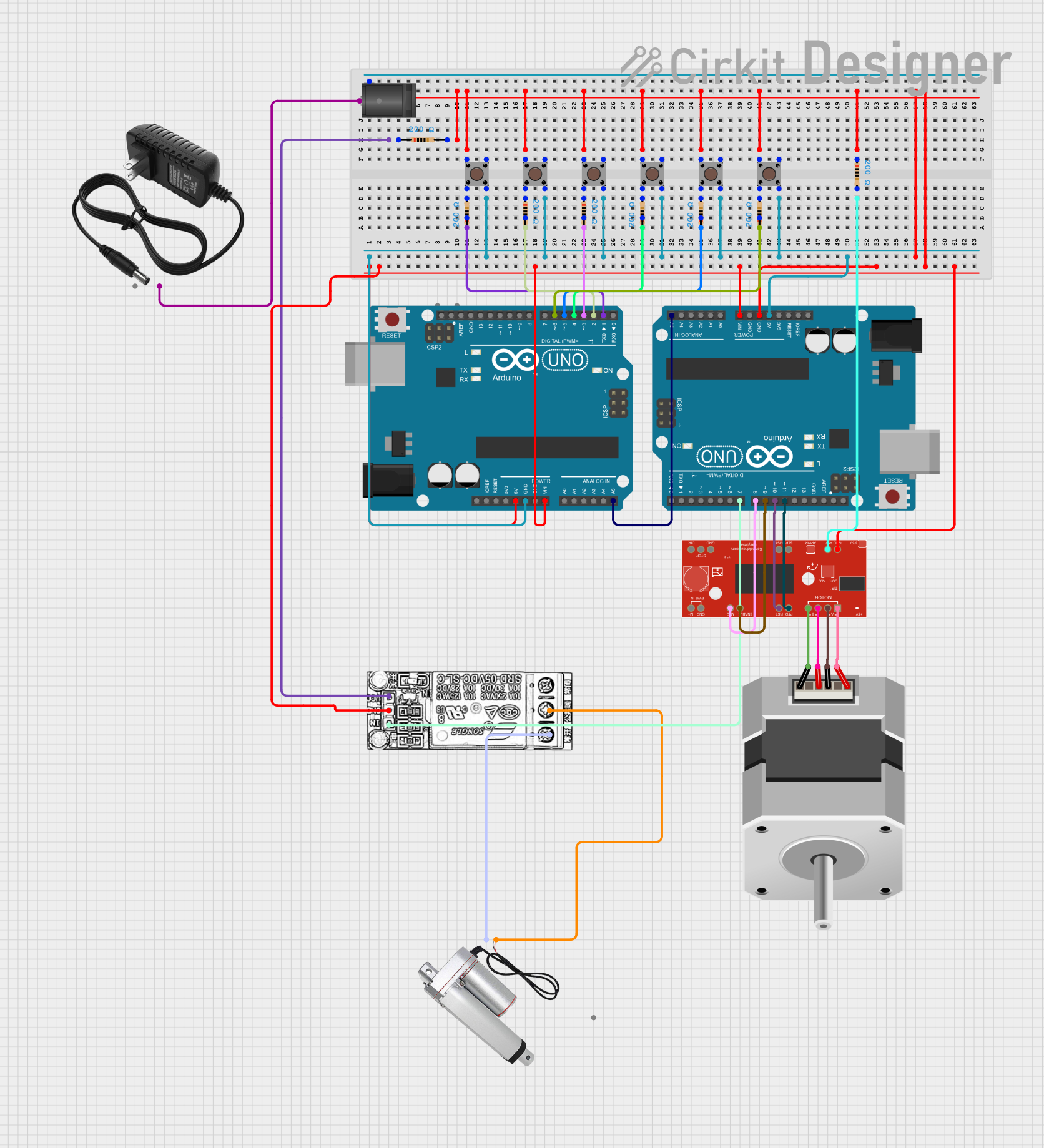

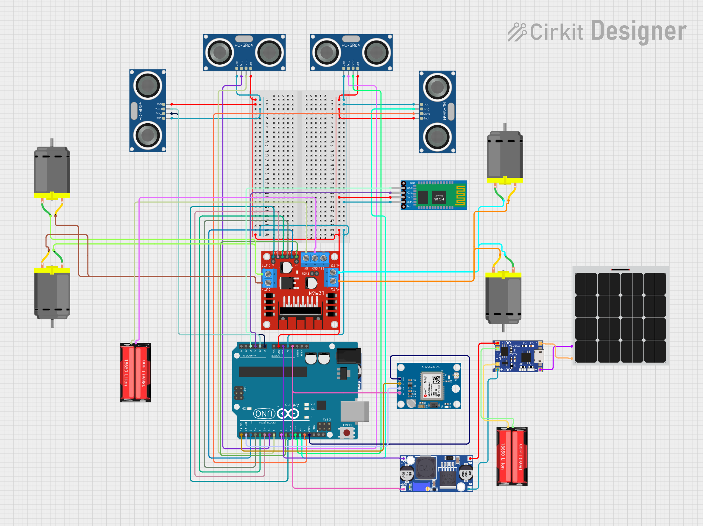
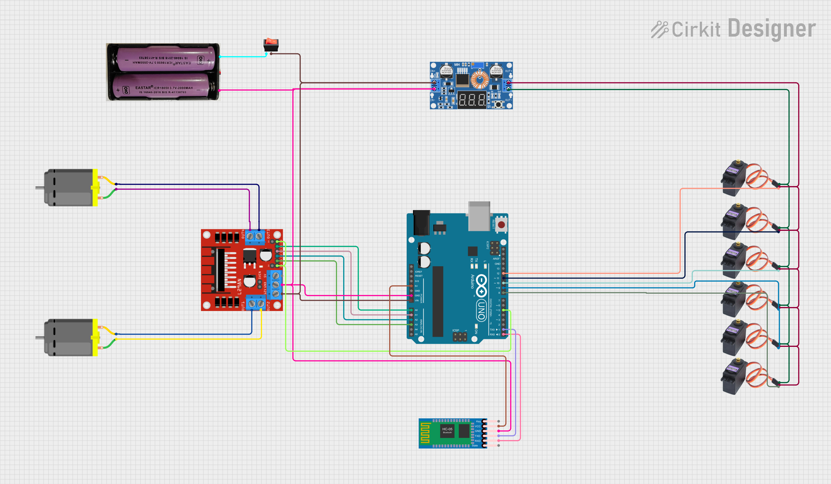
Explore Projects Built with EasyDriver_v45
Technical Specifications
Key Technical Details
- Logic Supply Voltage (VCC): 3V to 5.5V
- Motor Supply Voltage (VMOT): 6V to 30V
- Maximum Output Current: 750mA per phase without additional cooling
- Resolution: Full-step, Half-step, Quarter-step, and Eighth-step modes available
- Thermal Overload Protection: Yes
- Dimensions: 48mm x 20mm
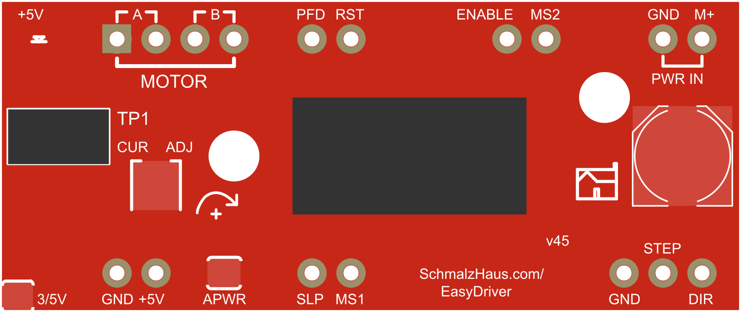
Pin Configuration and Descriptions
| Pin Name | Description |
|---|---|
| M+ | Motor power supply (6V to 30V) |
| GND | Ground connection |
| A+ | Motor coil A positive lead |
| A- | Motor coil A negative lead |
| B+ | Motor coil B positive lead |
| B- | Motor coil B negative lead |
| SLP | Sleep mode enable (active low) |
| RST | Reset pin (active low) |
| STEP | Step control input |
| DIR | Direction control input |
| MS1 | Microstep selection 1 |
| MS2 | Microstep selection 2 |
| ENABLE | Enable motor output (active low) |
Usage Instructions
Connecting the EasyDriver to a Stepper Motor
- Connect the motor's A and B coils to the A+ & A- and B+ & B- pins, respectively.
- Apply motor power to the M+ and GND pins, ensuring the voltage is within the specified range.
- Connect the logic power supply to the VCC and GND pins.
Setting Current Limit
- Turn the onboard potentiometer while measuring the voltage on the TP1 test point.
- Adjust the potentiometer to set the VREF to the desired level according to the formula:
VREF = (Current Limit) × 8 × Rs, where Rs is the current sense resistor value (0.1 ohms for EasyDriver v4.5).
Microstepping Configuration
- Set the MS1 and MS2 pins to either high or low to select the desired microstepping mode.
Interfacing with an Arduino UNO
// Define the connections to the EasyDriver board
const int dirPin = 2;  // Connect to DIR pin on EasyDriver
const int stepPin = 3; // Connect to STEP pin on EasyDriver

void setup() {
  pinMode(dirPin, OUTPUT);
  pinMode(stepPin, OUTPUT);
}

void loop() {
  digitalWrite(dirPin, HIGH); // Set the direction
  // Make one step:
  digitalWrite(stepPin, HIGH);
  delay(1); // Wait for 1 millisecond
  digitalWrite(stepPin, LOW);
  delay(1); // Wait for 1 millisecond
  // Repeat the above four lines to step the motor as needed
}
Important Considerations and Best Practices
- Always disconnect power before making or changing connections.
- Do not exceed the recommended voltage and current ratings.
- Use appropriate heat sinks if operating the motor at high currents.
- Ensure proper decoupling of the power supply to minimize voltage spikes.
Troubleshooting and FAQs
Common Issues
- Motor not moving: Check connections, ensure power supply is within range, and verify that the current limit is properly set.
- Motor getting hot: Adjust the current limit to a lower setting or improve cooling.
- Erratic motor behavior: Ensure that the microstepping pins are correctly set and that there is no noise in the control signals.
Solutions and Tips for Troubleshooting
- If the motor does not operate as expected, double-check the wiring and ensure that the control signals from the microcontroller are clean and noise-free.
- Use a multimeter to verify the voltage at the motor power supply and the VREF for current limit setting.
- Ensure that the logic supply voltage (VCC) is stable and within the specified range.
FAQs
Q: Can I drive two stepper motors with one EasyDriver board? A: No, the EasyDriver is designed to control a single bipolar stepper motor.
Q: What is the maximum step rate for the EasyDriver? A: The maximum step rate depends on the motor characteristics and the voltage applied. It is recommended to start with a low step rate and increase gradually to find the maximum rate for your specific setup.
Q: How do I enable half-stepping or quarter-stepping? A: Set the MS1 and MS2 pins to the appropriate logic levels according to the datasheet of the A4988 chip to enable different microstepping modes.
Q: Can I use the EasyDriver with a 3.3V logic level microcontroller? A: Yes, the EasyDriver can work with logic levels from 3V to 5.5V.
For further assistance, consult the EasyDriver community forums or contact technical support.