How to Use XBee3: Examples, Pinouts, and Specs
Introduction
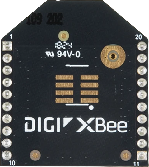
The XBee3 Module - PCB Antenna by Digi International is a compact, low-power wireless module designed for seamless communication in IoT applications. It supports multiple protocols, including Zigbee, DigiMesh, and Bluetooth Low Energy (BLE), making it a versatile choice for a wide range of wireless networking needs. The XBee3 is engineered for reliability, flexibility, and ease of integration, enabling developers to create robust and scalable IoT solutions.
Explore Projects Built with XBee3


Explore Projects Built with XBee3
Common Applications and Use Cases
- Smart Home Automation: Wireless control of lights, thermostats, and security systems.
- Industrial IoT: Remote monitoring and control of machinery and sensors.
- Agriculture: Wireless sensor networks for monitoring soil moisture, temperature, and other environmental factors.
- Healthcare: IoT-enabled medical devices for patient monitoring.
- Prototyping: Rapid development of wireless communication systems for IoT projects.
Technical Specifications
The XBee3 module is packed with features that make it ideal for IoT applications. Below are its key technical specifications:
General Specifications
| Parameter | Value |
|---|---|
| Manufacturer | Digi International |
| Part Number | XBee 3 Module - PCB Antenna |
| Wireless Protocols | Zigbee, DigiMesh, BLE |
| Frequency Band | 2.4 GHz |
| Data Rate | Up to 250 kbps (Zigbee) |
| Operating Voltage | 2.1V to 3.6V |
| Transmit Power | Up to +8 dBm |
| Receiver Sensitivity | -103 dBm (Zigbee) |
| Antenna Type | PCB Antenna |
| Dimensions | 13 mm x 19 mm |
| Operating Temperature | -40°C to +85°C |
Pin Configuration and Descriptions
The XBee3 module has a total of 20 pins. Below is the pinout and description:
| Pin Number | Pin Name | Description |
|---|---|---|
| 1 | VCC | Power supply input (2.1V to 3.6V). |
| 2 | DOUT | UART Data Out. Transmits serial data to the host microcontroller. |
| 3 | DIN | UART Data In. Receives serial data from the host microcontroller. |
| 4 | DIO4 | Digital I/O or ADC input. |
| 5 | RESET | Reset input. Active low. |
| 6 | DIO0/AD0 | Digital I/O or ADC input. |
| 7 | DIO1/AD1 | Digital I/O or ADC input. |
| 8 | DIO2/AD2 | Digital I/O or ADC input. |
| 9 | DIO3/AD3 | Digital I/O or ADC input. |
| 10 | GND | Ground. |
| 11 | DIO5/ASSOCIATE | Digital I/O or network association indicator. |
| 12 | DIO6 | Digital I/O. |
| 13 | DIO7 | Digital I/O. |
| 14 | DIO8 | Digital I/O. |
| 15 | DIO9 | Digital I/O. |
| 16 | DIO10 | Digital I/O. |
| 17 | DIO11 | Digital I/O. |
| 18 | DIO12 | Digital I/O. |
| 19 | DIO13 | Digital I/O. |
| 20 | NC | Not connected. |
Usage Instructions
The XBee3 module is easy to integrate into a circuit and can be configured for various wireless communication protocols. Below are the steps to use the module effectively:
Step 1: Hardware Setup
- Power Supply: Connect the VCC pin to a regulated 3.3V power source and the GND pin to ground.
- UART Communication: Connect the DOUT pin to the RX pin of your microcontroller and the DIN pin to the TX pin of your microcontroller.
- Reset: Optionally, connect the RESET pin to a GPIO pin on your microcontroller for manual or software-controlled resets.
- I/O Pins: Use the digital I/O pins (DIO0 to DIO13) for additional functionality, such as reading sensors or controlling actuators.
Step 2: Configuration
The XBee3 module can be configured using Digi's XCTU software:
- Download and install XCTU from Digi's website.
- Connect the XBee3 module to your computer using an XBee USB adapter.
- Launch XCTU and detect the module.
- Configure the module's settings, such as PAN ID, channel, and communication protocol (e.g., Zigbee or DigiMesh).
Step 3: Example with Arduino UNO
The XBee3 module can be interfaced with an Arduino UNO for wireless communication. Below is an example code snippet for sending data:
#include <SoftwareSerial.h>

// Define RX and TX pins for SoftwareSerial
SoftwareSerial XBee(2, 3); // RX = Pin 2, TX = Pin 3

void setup() {
  Serial.begin(9600);       // Initialize Serial Monitor
  XBee.begin(9600);         // Initialize XBee communication
  Serial.println("XBee3 Module Test");
}

void loop() {
  // Send data to XBee
  XBee.println("Hello, XBee!");
  Serial.println("Data sent to XBee: Hello, XBee!");

  // Check for incoming data from XBee
  if (XBee.available()) {
    String receivedData = XBee.readString();
    Serial.print("Data received from XBee: ");
    Serial.println(receivedData);
  }

  delay(1000); // Wait for 1 second
}
Important Considerations
- Ensure the module's operating voltage does not exceed 3.6V to avoid damage.
- Use level shifters if interfacing with a 5V microcontroller.
- Configure the same PAN ID and channel for all XBee modules in the network.
- Place the module away from sources of interference, such as high-power RF devices.
Troubleshooting and FAQs
Common Issues and Solutions
Module Not Responding:
- Ensure the module is powered correctly (check VCC and GND connections).
- Verify the UART connections (DOUT to RX and DIN to TX).
- Check the baud rate settings in your code and XCTU.
No Communication Between Modules:
- Ensure all modules are configured with the same PAN ID and channel.
- Verify the communication protocol (e.g., Zigbee or DigiMesh) is consistent across modules.
- Check for physical obstructions or interference in the environment.
Data Loss or Corruption:
- Reduce the data rate or increase the delay between transmissions.
- Ensure the modules are within the specified range (up to 120 meters indoors).
FAQs
Q: Can the XBee3 module be used with a 5V microcontroller?
A: Yes, but you must use level shifters to step down the 5V signals to 3.3V for the XBee3 module.
Q: How do I reset the module to factory settings?
A: Use the XCTU software to perform a factory reset or hold the RESET pin low for a few seconds.
Q: What is the maximum range of the XBee3 module?
A: The range is up to 120 meters indoors and 1,200 meters outdoors (line of sight) under ideal conditions.
Q: Can I use the XBee3 module for Bluetooth communication?
A: Yes, the XBee3 supports BLE for short-range communication. Configure it via XCTU.