How to Use Adafruit TPL5110 Power Timer: Examples, Pinouts, and Specs
Introduction
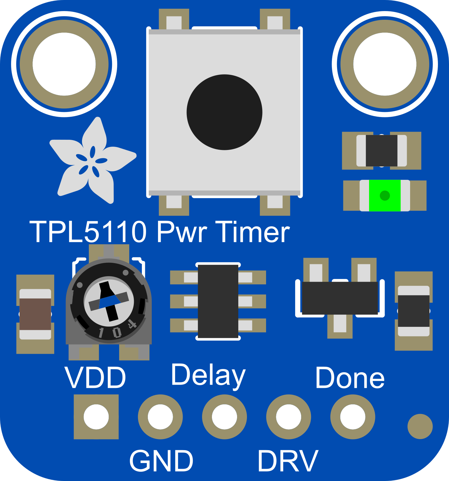
The Adafruit TPL5110 Power Timer is a breakout board designed around the TPL5110 low power timer Integrated Circuit (IC). This component is essential for power management in battery-powered or energy-conserving applications. It enables projects to enter a low-power mode, significantly extending the battery life by powering down the system for set intervals and only waking it when necessary.
Explore Projects Built with Adafruit TPL5110 Power Timer

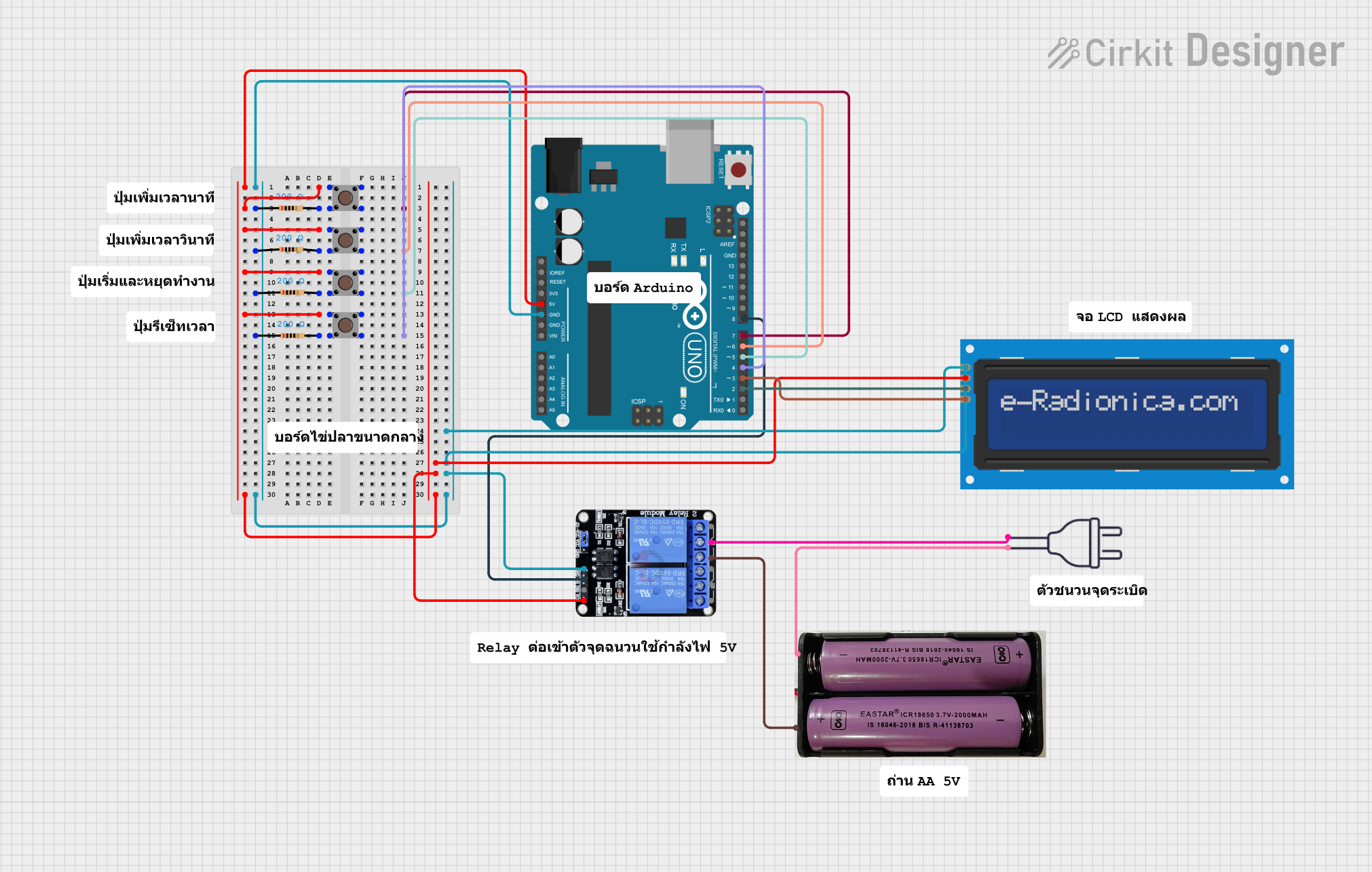
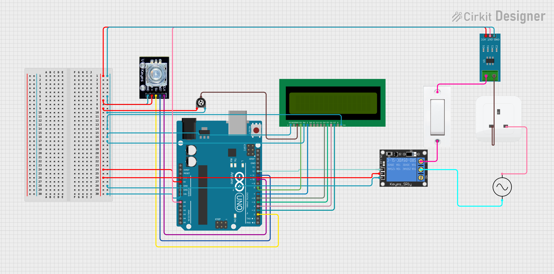
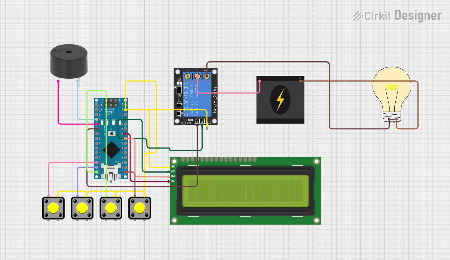
Explore Projects Built with Adafruit TPL5110 Power Timer
Common Applications and Use Cases
- Battery-powered IoT devices
- Periodic data logging systems
- Environmental monitoring stations
- Wildlife tracking devices
- Remote sensors
- Power cycling of electronics for reset purposes
Technical Specifications
Key Technical Details
- Voltage Range: 1.8V to 5.5V
- Max Current: 20 mA
- Timer Delay Range: 100ms to 7200s (2 hours)
- Operating Temperature: -40°C to 85°C
Pin Configuration and Descriptions
| Pin Number | Name | Description |
|---|---|---|
| 1 | GND | Ground connection |
| 2 | VIN | Voltage input (1.8V to 5.5V) |
| 3 | GATE | Drives an external N-channel MOSFET to control power to your project |
| 4 | DONE | Signal input to stop the timer and set the system into a low-power state |
| 5 | DRV | Open-drain output to indicate the timer has finished |
| 6 | DELAY | Sets the delay interval with an external resistor |
Usage Instructions
How to Use the Component in a Circuit
- Power Connection: Connect the VIN pin to your power source (1.8V to 5.5V) and the GND pin to the ground.
- Load Control: Connect the GATE pin to the gate of an N-channel MOSFET, which controls the power to your load.
- Setting the Timer: Connect a resistor between the DELAY pin and ground to set the desired delay interval.
- Starting the Timer: Power the TPL5110, and it will start the timer automatically.
- Stopping the Timer: Send a low pulse to the DONE pin to stop the timer and put the system into a low-power state.
Important Considerations and Best Practices
- Ensure that the power supply voltage does not exceed the maximum rating of 5.5V.
- Select a MOSFET that can handle the current requirements of your load.
- Use a pull-up resistor on the DRV pin if you need a logic-level signal.
- Calculate the delay resistor value accurately based on the desired timing interval.
- Avoid placing the timer in environments exceeding the specified temperature range.
Example Code for Arduino UNO
// Example code to interface with the Adafruit TPL5110 Power Timer using an Arduino UNO

const int donePin = 2; // Connect to the DONE pin of the TPL5110

void setup() {
  pinMode(donePin, OUTPUT);
  digitalWrite(donePin, HIGH); // Start with the timer stopped
}

void loop() {
  // Your main code would go here

  // Signal the TPL5110 that the task is done
  digitalWrite(donePin, LOW);
  delay(100); // Wait for 100ms to ensure the signal is registered
  digitalWrite(donePin, HIGH);

  // Enter a low-power state until the TPL5110 wakes the system
  // Note: The Arduino itself does not go into a low-power state without additional code
  delay(10000); // Placeholder for low-power mode
}
Troubleshooting and FAQs
Common Issues
- Timer Not Starting: Ensure that the power supply is within the specified range and connections are secure.
- Load Not Powering On: Check the MOSFET and its connections, and ensure that the GATE pin is being driven correctly.
- Incorrect Timing Intervals: Verify the resistor value connected to the DELAY pin and recalculate if necessary.
Solutions and Tips for Troubleshooting
- Double-check all connections and solder joints for continuity and shorts.
- Use a multimeter to measure the voltage at the VIN pin and the resistance at the DELAY pin.
- If the timer is not stopping, ensure that the DONE pin is receiving a clear low pulse.
FAQs
Q: Can I use the TPL5110 to wake up my microcontroller? A: Yes, the DRV pin can be connected to an interrupt pin on your microcontroller to wake it up when the timer expires.
Q: How do I calculate the resistor value for the DELAY pin? A: Use the formula provided in the TPL5110 datasheet, or refer to Adafruit's TPL5110 guide for a table of resistor values and corresponding delays.
Q: Is it possible to reprogram the delay interval on-the-fly? A: The delay interval is set by a physical resistor, so it cannot be changed programmatically. You would need to replace the resistor to change the delay.
Q: What is the power consumption of the TPL5110 in low-power mode? A: The TPL5110 consumes very low power in its low-power state, typically in the range of 35 nA, making it ideal for battery-powered applications.
For further assistance, consult the Adafruit TPL5110 datasheet and Adafruit's learning resources.