
How to Use Turbidity: Examples, Pinouts, and Specs
 Design with Turbidity in Cirkit Designer
Introduction
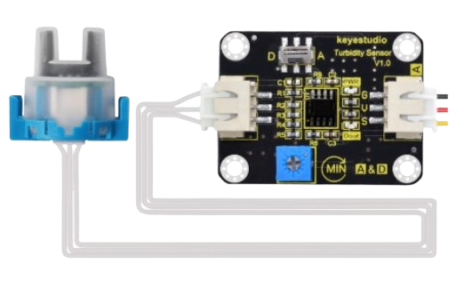
The Arduino Turbidity Sensor (Part ID: 1) is a device designed to measure the cloudiness or haziness of a liquid. This property, known as turbidity, is often used as an indicator of water quality. The sensor detects the presence of suspended particles in a liquid by measuring the amount of light that passes through it. The more particles present, the higher the turbidity and the lower the light transmission.
Explore Projects Built with Turbidity
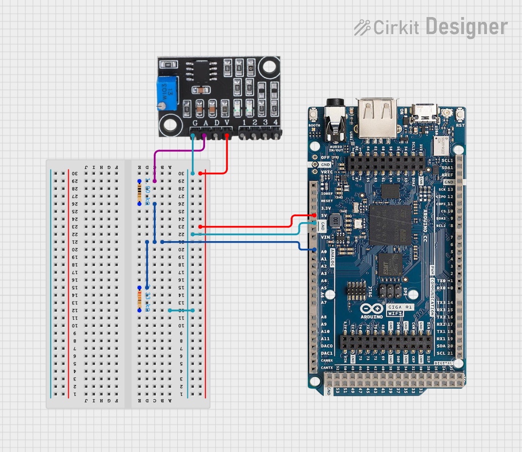 Open Project in Cirkit Designer
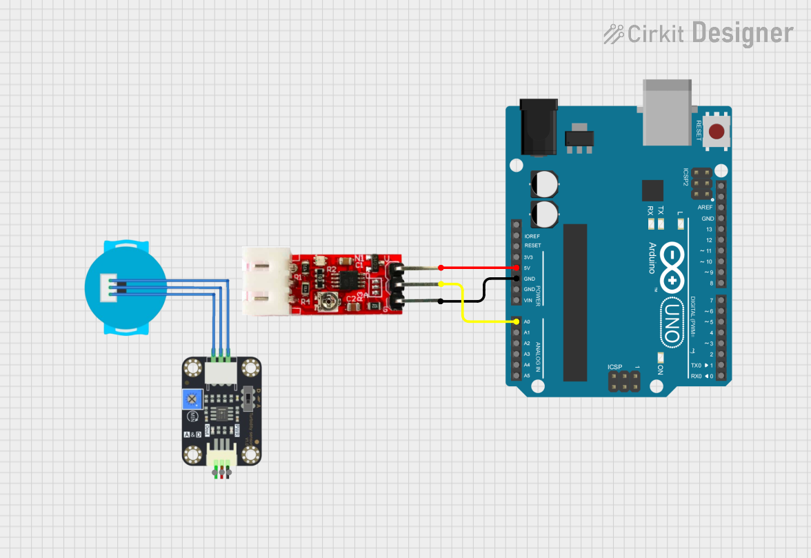 Open Project in Cirkit Designer
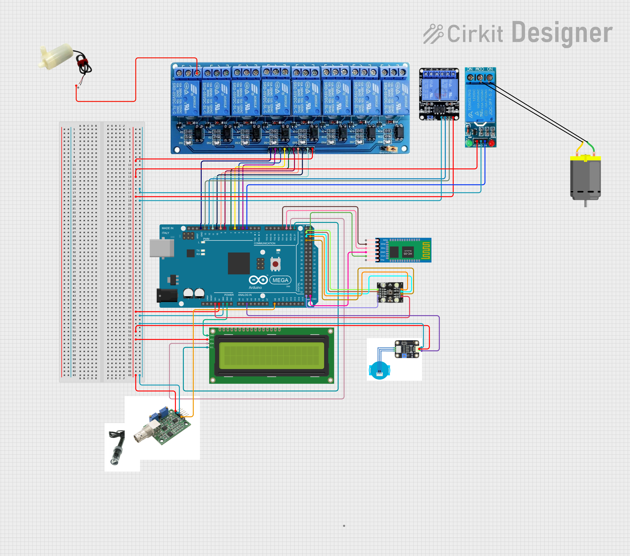 Open Project in Cirkit Designer
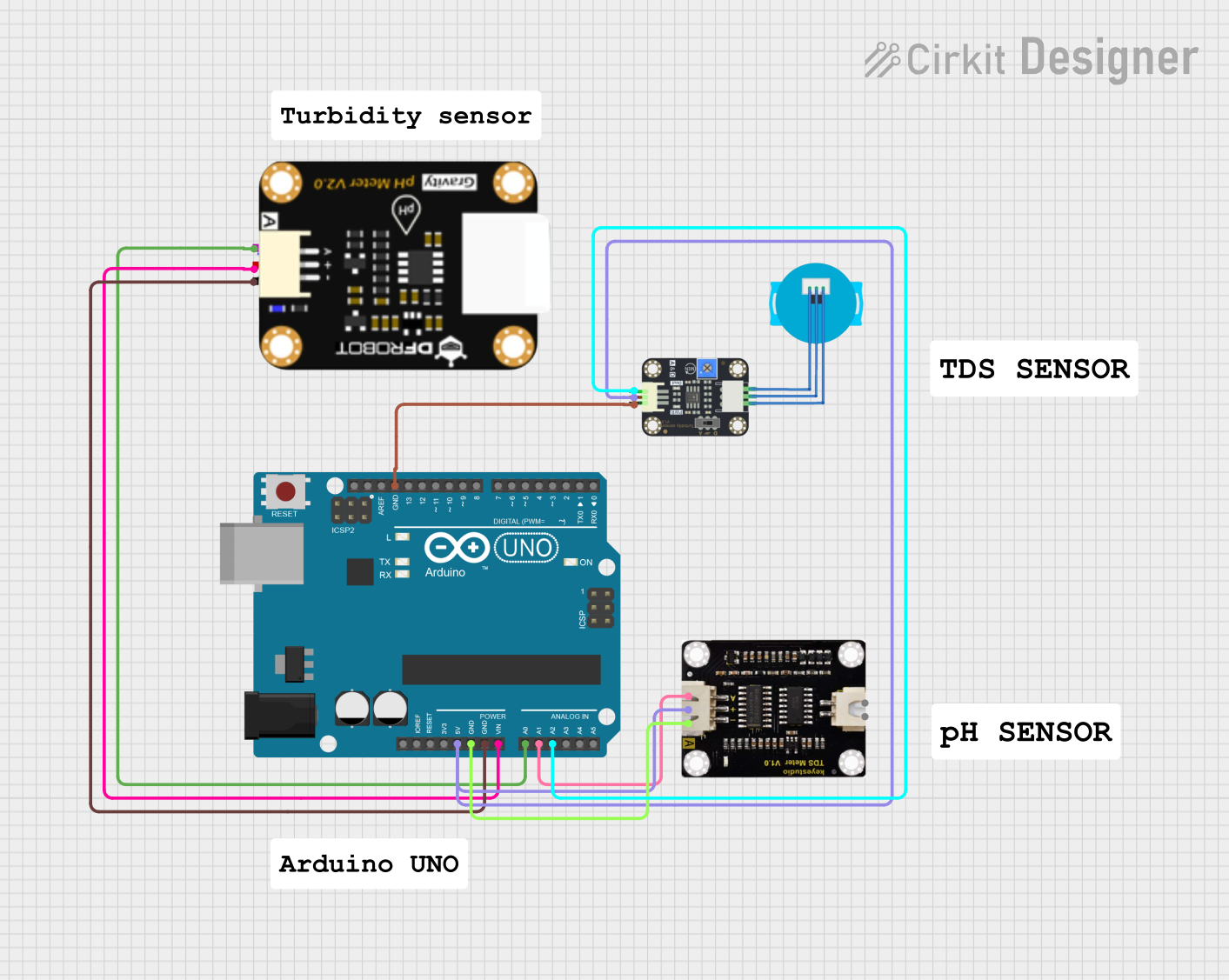 Open Project in Cirkit Designer
Explore Projects Built with Turbidity
Open Project in Cirkit DesignerOpen Project in Cirkit DesignerOpen Project in Cirkit DesignerOpen Project in Cirkit DesignerCommon Applications and Use Cases
- Water quality monitoring in environmental studies
- Industrial process control in water treatment plants
- Aquatic ecosystem analysis
- Aquarium and hydroponics system maintenance
- Food and beverage quality testing
Technical Specifications
The Arduino Turbidity Sensor is designed for ease of use and compatibility with microcontrollers like the Arduino UNO. Below are its key technical details:
General Specifications
| Parameter | Value |
|---|---|
| Operating Voltage | 5V DC |
| Operating Current | 30mA |
| Output Signal | Analog (0-4.5V) |
| Measurement Range | 0-1000 NTU (Nephelometric Turbidity Units) |
| Operating Temperature | -30°C to 80°C |
| Storage Temperature | -10°C to 80°C |
| Response Time | < 500ms |
Pin Configuration and Descriptions
| Pin Name | Pin Type | Description |
|---|---|---|
| VCC | Power | Connect to 5V DC power supply |
| GND | Ground | Connect to ground |
| AOUT | Analog Out | Outputs an analog voltage proportional to turbidity |
| DOUT | Digital Out | Outputs a digital signal (high/low) based on a threshold |
Usage Instructions
How to Use the Turbidity Sensor in a Circuit
Wiring the Sensor:
- Connect the
VCCpin of the sensor to the 5V pin on the Arduino UNO. - Connect the
GNDpin of the sensor to the GND pin on the Arduino UNO. - Connect the
AOUTpin of the sensor to an analog input pin (e.g., A0) on the Arduino UNO. - Optionally, connect the
DOUTpin to a digital input pin if you want to use the digital threshold feature.
- Connect the
Calibrating the Sensor:
- Place the sensor in a liquid with known turbidity (e.g., distilled water for 0 NTU).
- Record the analog output voltage for reference.
- Repeat the process with a liquid of higher turbidity to establish a calibration curve.
Reading Data:
- Use the Arduino IDE to write a program that reads the analog voltage from the sensor.
- Convert the voltage reading into turbidity (NTU) using the calibration data.
Important Considerations and Best Practices
- Ensure the sensor is fully submerged in the liquid for accurate readings.
- Avoid exposing the sensor to direct sunlight or strong ambient light, as this may affect measurements.
- Clean the sensor regularly to prevent fouling or buildup of particles on the optical surface.
- Use a stable 5V power supply to minimize noise in the output signal.
- If using the digital output, adjust the onboard potentiometer to set the desired turbidity threshold.
Sample Arduino Code
Below is an example of how to interface the turbidity sensor with an Arduino UNO:
// Turbidity Sensor Example Code
// Reads analog output from the sensor and converts it to NTU (Nephelometric Turbidity Units)

const int sensorPin = A0; // Analog pin connected to AOUT of the sensor
float voltage = 0;        // Variable to store sensor voltage
float turbidity = 0;      // Variable to store calculated turbidity (NTU)

void setup() {
  Serial.begin(9600); // Initialize serial communication at 9600 baud
}

void loop() {
  // Read the analog voltage from the sensor
  int sensorValue = analogRead(sensorPin);

  // Convert the analog value (0-1023) to voltage (0-5V)
  voltage = sensorValue * (5.0 / 1023.0);

  // Convert voltage to turbidity (NTU) using a calibration formula
  // Example formula: turbidity = -1120.4 * voltage^2 + 5742.3 * voltage - 4352.9
  // Replace with your own calibration data if available
  turbidity = -1120.4 * pow(voltage, 2) + 5742.3 * voltage - 4352.9;

  // Print the results to the Serial Monitor
  Serial.print("Voltage: ");
  Serial.print(voltage);
  Serial.print(" V, Turbidity: ");
  Serial.print(turbidity);
  Serial.println(" NTU");

  delay(1000); // Wait for 1 second before the next reading
}
Troubleshooting and FAQs
Common Issues and Solutions
No Output or Incorrect Readings:
- Cause: Loose or incorrect wiring.
- Solution: Double-check all connections and ensure the sensor is powered.
Fluctuating Readings:
- Cause: Electrical noise or unstable power supply.
- Solution: Use a decoupling capacitor (e.g., 0.1µF) across the power pins to stabilize the voltage.
Sensor Not Responding to Changes in Turbidity:
- Cause: Dirty or obstructed optical surface.
- Solution: Clean the sensor with a soft cloth and distilled water.
Digital Output Not Triggering:
- Cause: Incorrect threshold setting.
- Solution: Adjust the potentiometer on the sensor module to set the desired threshold.
FAQs
Q1: Can the sensor be used with liquids other than water?
A1: Yes, but the calibration curve may vary depending on the liquid's properties. Ensure the liquid is compatible with the sensor's materials.
Q2: How do I extend the sensor's lifespan?
A2: Avoid prolonged exposure to corrosive or abrasive liquids, and clean the sensor regularly to prevent buildup.
Q3: Can I use the sensor with a 3.3V microcontroller?
A3: The sensor is designed for 5V operation. Use a level shifter or voltage regulator if interfacing with a 3.3V system.
Q4: What is the maximum cable length for the sensor?
A4: For best performance, keep the cable length under 1 meter to minimize signal degradation. Use shielded cables for longer distances.