Cirkit Designer
Your all-in-one circuit design IDE
Home /
Component Documentation
How to Use SparkFun Wireless JoyStick: Examples, Pinouts, and Specs
Introduction
The SparkFun Wireless JoyStick is a versatile and user-friendly wireless controller designed for hobbyists and professionals alike. It enables wireless control for a variety of projects, such as robotics, remote-controlled vehicles, and interactive installations. The joystick provides analog input while the buttons allow for digital input, making it a flexible solution for many applications.
Explore Projects Built with SparkFun Wireless JoyStick
Arduino Nano Joystick-Controlled Bluetooth Module with Battery Power

This circuit is a wireless joystick controller that uses an Arduino Nano to read analog signals from a KY-023 Dual Axis Joystick Module and transmits the data via an HC-05 Bluetooth Module. The system is powered by a 18650 Li-Ion battery with a rocker switch for power control.
Arduino Nano Controlled Joystick with NRF24L01 Wireless Communication
This circuit features an Arduino Nano microcontroller interfaced with an NRF24L01 wireless communication module and a KY-023 Dual Axis Joystick Module. The Arduino Nano is powered by a 12V battery through a rocker switch, and it communicates with the NRF24L01 to potentially send joystick position data wirelessly. The joystick module provides analog input to the Arduino for two axes, and the NRF24L01 is connected via SPI for wireless data transmission.
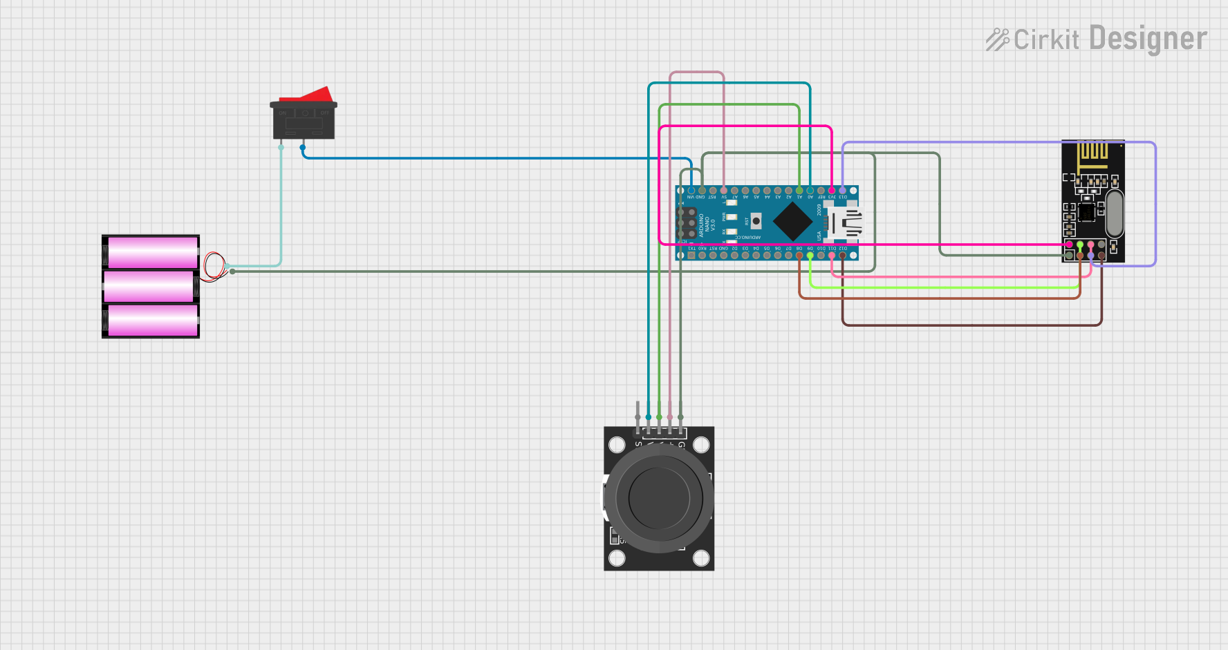
Wireless Joystick-Controlled Interface with Arduino Nano and NRF24L01

This circuit features an Arduino Nano interfaced with a KY-023 Dual Axis Joystick Module for analog input, and an NRF24L01 module for wireless communication. The joystick provides x and y-axis control signals to the Arduino's analog inputs and a switch signal to a digital input, while the NRF24L01 enables the Arduino to communicate with other devices wirelessly. The 2x 18650 batteries supply power to the Arduino, which in turn powers the joystick and the NRF24L01 module.
Arduino Nano Controlled Dual Joystick Interface with NRF24L01 Wireless Communication
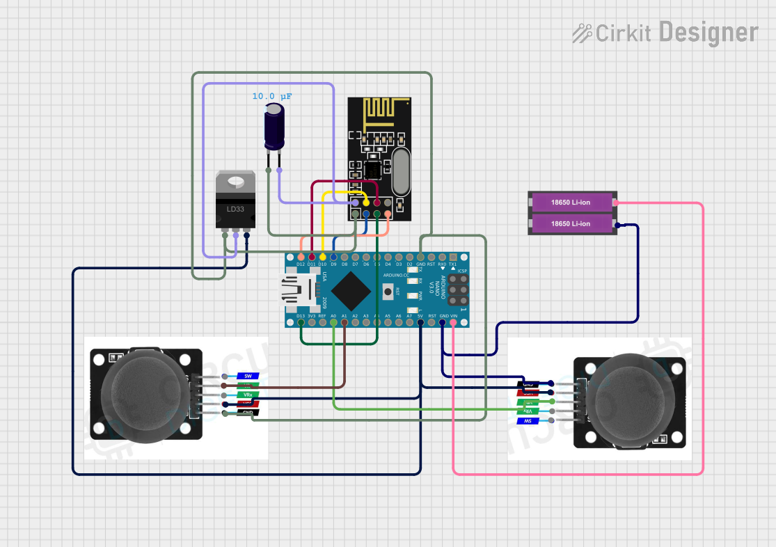
This circuit features an Arduino Nano microcontroller interfaced with two joystick modules for user input, an NRF24L01 module for wireless communication, and a pair of 18650 Li-ion batteries for power, regulated by an LD33 voltage regulator. The joysticks' variable resistors are connected to the Arduino's analog inputs for position sensing, while the NRF24L01 is connected via SPI to facilitate wireless data transmission. An electrolytic capacitor is used to stabilize the NRF24L01's power supply.
Explore Projects Built with SparkFun Wireless JoyStick
Arduino Nano Joystick-Controlled Bluetooth Module with Battery Power
This circuit is a wireless joystick controller that uses an Arduino Nano to read analog signals from a KY-023 Dual Axis Joystick Module and transmits the data via an HC-05 Bluetooth Module. The system is powered by a 18650 Li-Ion battery with a rocker switch for power control.
Arduino Nano Controlled Joystick with NRF24L01 Wireless Communication
This circuit features an Arduino Nano microcontroller interfaced with an NRF24L01 wireless communication module and a KY-023 Dual Axis Joystick Module. The Arduino Nano is powered by a 12V battery through a rocker switch, and it communicates with the NRF24L01 to potentially send joystick position data wirelessly. The joystick module provides analog input to the Arduino for two axes, and the NRF24L01 is connected via SPI for wireless data transmission.
Wireless Joystick-Controlled Interface with Arduino Nano and NRF24L01
This circuit features an Arduino Nano interfaced with a KY-023 Dual Axis Joystick Module for analog input, and an NRF24L01 module for wireless communication. The joystick provides x and y-axis control signals to the Arduino's analog inputs and a switch signal to a digital input, while the NRF24L01 enables the Arduino to communicate with other devices wirelessly. The 2x 18650 batteries supply power to the Arduino, which in turn powers the joystick and the NRF24L01 module.
Arduino Nano Controlled Dual Joystick Interface with NRF24L01 Wireless Communication
This circuit features an Arduino Nano microcontroller interfaced with two joystick modules for user input, an NRF24L01 module for wireless communication, and a pair of 18650 Li-ion batteries for power, regulated by an LD33 voltage regulator. The joysticks' variable resistors are connected to the Arduino's analog inputs for position sensing, while the NRF24L01 is connected via SPI to facilitate wireless data transmission. An electrolytic capacitor is used to stabilize the NRF24L01's power supply.
Common Applications and Use Cases
- Remote control for robots or drones
- Wireless game controller for custom gaming setups
- Interactive exhibits and installations
- DIY electronics projects requiring user input
Technical Specifications
Key Technical Details
- Communication: RF (Radio Frequency) transmission
- Operating Voltage: 3.3V to 5V
- Frequency: 2.4 GHz
- Number of Channels: Multiple channels for minimal interference
- Range: Up to 10 meters (without obstacles)
- Interface: Analog (joystick), Digital (buttons)
- Power: Typically powered by AA or AAA batteries
Pin Configuration and Descriptions
| Pin | Description |
|---|---|
| VCC | Power supply (3.3V to 5V) |
| GND | Ground connection |
| VRx | Joystick X-axis analog voltage output |
| VRy | Joystick Y-axis analog voltage output |
| SW | Joystick pushbutton switch |
| BTN | Additional buttons (labeled on the board) |
Usage Instructions
How to Use the Component in a Circuit
- Powering the Device: Connect the VCC pin to a 3.3V or 5V power supply and the GND pin to the ground.
- Connecting the Joystick: Connect the VRx and VRy pins to the analog inputs of your microcontroller to read the joystick's position.
- Reading Button Presses: Connect the SW and BTN pins to the digital inputs of your microcontroller to detect button presses.
- Pairing with Receiver: Ensure that the RF receiver is properly connected to your project and is on the same frequency as the Wireless JoyStick.
Important Considerations and Best Practices
- Always ensure that the power supply is within the specified voltage range to prevent damage.
- When using with an Arduino UNO, remember to calibrate the joystick's analog readings for accurate control.
- To minimize interference, select a channel that is not being used by other wireless devices in the vicinity.
- For battery-powered projects, monitor the battery level to maintain reliable communication.
Example Code for Arduino UNO
#include <SPI.h>

// Define joystick and button pins
const int joystickX = A0;
const int joystickY = A1;
const int buttonPin = 2;

void setup() {
  // Initialize serial communication
  Serial.begin(9600);

  // Set button pin as input
  pinMode(buttonPin, INPUT_PULLUP);
}

void loop() {
  // Read the joystick values
  int xValue = analogRead(joystickX);
  int yValue = analogRead(joystickY);

  // Read the button state
  bool buttonState = digitalRead(buttonPin);

  // Print the joystick values and button state
  Serial.print("X: ");
  Serial.print(xValue);
  Serial.print(" Y: ");
  Serial.print(yValue);
  Serial.print(" Button: ");
  Serial.println(buttonState);

  // Add a delay before the next reading
  delay(100);
}
Troubleshooting and FAQs
Common Issues Users Might Face
- Intermittent Connection: Ensure that the batteries are fully charged and the receiver is within range.
- Inaccurate Joystick Readings: Calibrate the joystick by mapping the analog readings to your system's requirements.
- No Response from Buttons: Check the button connections and ensure they are configured correctly in your code.
Solutions and Tips for Troubleshooting
- Battery Issues: Replace batteries or use a stable power supply to ensure consistent operation.
- Signal Interference: Change the operating channel or move away from devices that may cause interference.
- Connection Problems: Verify all connections and ensure that the receiver module is correctly paired with the joystick.
FAQs
Q: Can I use multiple Wireless JoySticks with one receiver?
- A: Yes, but each joystick must be set to a different channel to avoid interference.
Q: What is the maximum range of the Wireless JoyStick?
- A: The maximum range is up to 10 meters in an open area without obstacles.
Q: How do I know if the joystick is properly connected to my Arduino?
- A: Run the example code provided and observe the serial monitor for joystick and button readings.