How to Use CD4093: Examples, Pinouts, and Specs
Introduction
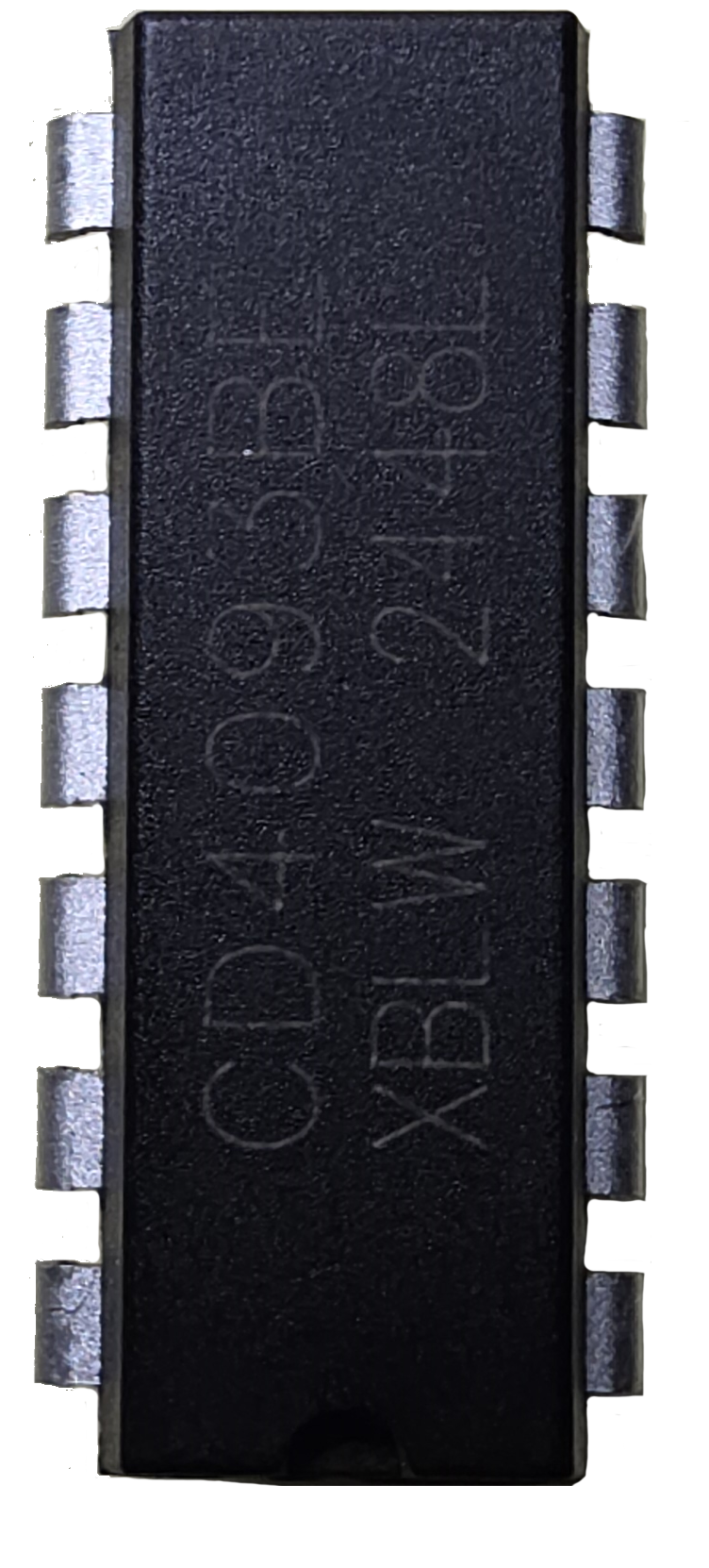
The CD4093, manufactured by Texas Instruments, is a quad 2-input NAND Schmitt trigger. This versatile component is designed to provide stable output signals even in the presence of noisy or slow-changing input signals. Each of the four independent gates in the CD4093 integrates Schmitt trigger functionality, ensuring high noise immunity and fast switching times.
Explore Projects Built with CD4093
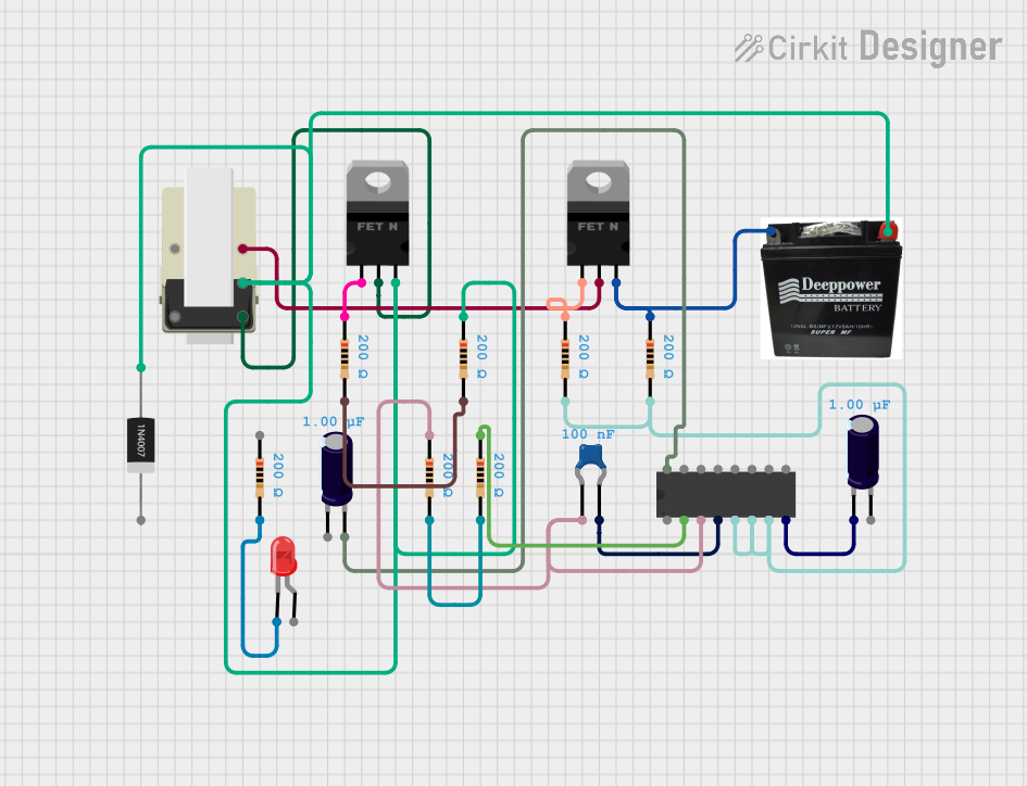
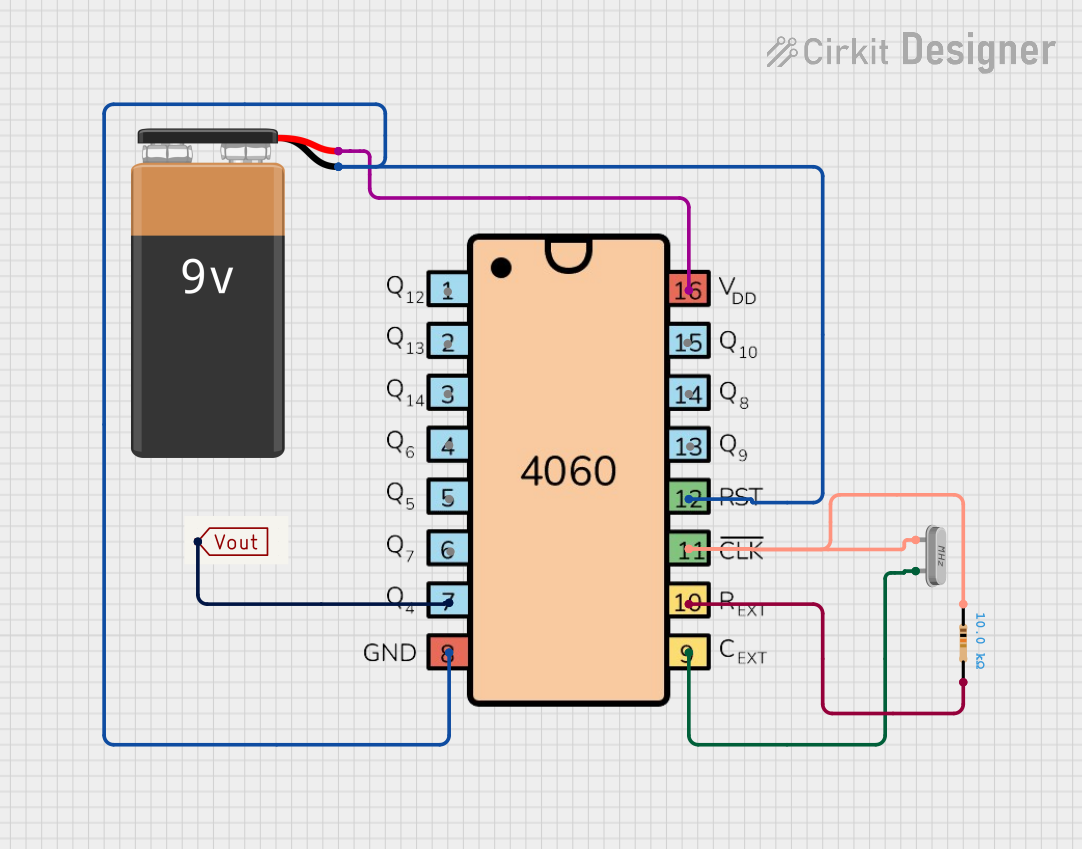


Explore Projects Built with CD4093
Common Applications and Use Cases
- Waveform shaping and signal conditioning
- Oscillator circuits
- Pulse generation and timing circuits
- Logic-level conversion
- Debouncing mechanical switches
- General-purpose digital logic applications
Technical Specifications
Key Technical Details
- Supply Voltage (VDD): 3V to 15V
- Input Voltage Range (VIN): 0V to VDD
- Output Voltage (VOUT): 0V to VDD
- High-Level Output Current (IOH): -1.5mA (at VDD = 5V)
- Low-Level Output Current (IOL): 1.5mA (at VDD = 5V)
- Propagation Delay: ~200ns (typical at VDD = 5V)
- Quiescent Current (IQ): 1µA (maximum at VDD = 5V)
- Operating Temperature Range: -55°C to 125°C
- Package Types: PDIP, SOIC, TSSOP
Pin Configuration and Descriptions
The CD4093 is a 14-pin IC. Below is the pinout and description:
| Pin Number | Pin Name | Description |
|---|---|---|
| 1 | 1A | Input A for Gate 1 |
| 2 | 1B | Input B for Gate 1 |
| 3 | 1Y | Output of Gate 1 |
| 4 | 2A | Input A for Gate 2 |
| 5 | 2B | Input B for Gate 2 |
| 6 | 2Y | Output of Gate 2 |
| 7 | VSS | Ground (0V) |
| 8 | 3Y | Output of Gate 3 |
| 9 | 3A | Input A for Gate 3 |
| 10 | 3B | Input B for Gate 3 |
| 11 | 4Y | Output of Gate 4 |
| 12 | 4A | Input A for Gate 4 |
| 13 | 4B | Input B for Gate 4 |
| 14 | VDD | Positive Supply Voltage |
Usage Instructions
How to Use the CD4093 in a Circuit
- Power Supply: Connect the VDD pin (Pin 14) to the positive supply voltage (3V to 15V) and the VSS pin (Pin 7) to ground.
- Inputs: Apply the input signals to the A and B pins of the desired gate. The Schmitt trigger functionality ensures stable operation even with noisy or slow-changing inputs.
- Outputs: The output of each gate (Y pin) will follow the NAND logic with Schmitt trigger characteristics. For example, the output will be LOW only when both inputs are HIGH.
- Load: Connect the output to the desired load, ensuring it does not exceed the maximum current rating of the IC.
Example Circuit: Oscillator Using CD4093
The CD4093 can be used to create a simple square wave oscillator. Below is an example circuit and Arduino code to measure the frequency of the generated signal.
Circuit Diagram
- Connect a resistor (R) between the output (1Y) and input A (1A) of Gate 1.
- Connect a capacitor (C) between input A (1A) and ground.
- Connect input B (1B) of Gate 1 to VDD.
- The output (1Y) will generate a square wave.
Arduino Code to Measure Frequency
// This code measures the frequency of the square wave generated by the CD4093
// and displays it on the Serial Monitor.

const int inputPin = 2; // Connect the CD4093 output to Arduino pin 2

void setup() {
  pinMode(inputPin, INPUT); // Set the pin as input
  Serial.begin(9600);       // Initialize serial communication
}

void loop() {
  unsigned long duration = pulseIn(inputPin, HIGH);
  // Measure the HIGH pulse duration in microseconds

  if (duration > 0) {
    float frequency = 1000000.0 / (2 * duration);
    // Calculate frequency in Hz (1/period)

    Serial.print("Frequency: ");
    Serial.print(frequency);
    Serial.println(" Hz");
  }
  delay(500); // Wait for half a second before the next measurement
}
Important Considerations and Best Practices
- Input Voltage Levels: Ensure that the input voltage does not exceed the supply voltage (VDD).
- Unused Inputs: Tie unused inputs to VDD or VSS to prevent floating inputs, which can cause erratic behavior.
- Decoupling Capacitor: Place a 0.1µF ceramic capacitor close to the VDD pin to filter noise and stabilize the power supply.
- Load Current: Do not exceed the maximum output current rating to avoid damaging the IC.
Troubleshooting and FAQs
Common Issues and Solutions
No Output Signal:
- Verify that the power supply is connected correctly to VDD and VSS.
- Check that the input signals meet the required voltage levels.
- Ensure that the load connected to the output does not exceed the IC's current rating.
Erratic Behavior:
- Add a decoupling capacitor (0.1µF) near the IC to reduce power supply noise.
- Tie unused inputs to VDD or VSS to prevent floating inputs.
Incorrect Output Logic:
- Double-check the input connections and ensure they follow the NAND logic truth table.
- Verify that the input signals are within the Schmitt trigger thresholds.
FAQs
Q: Can the CD4093 operate at 3.3V?
A: Yes, the CD4093 can operate with a supply voltage as low as 3V, making it compatible with 3.3V systems.
Q: What is the advantage of the Schmitt trigger in the CD4093?
A: The Schmitt trigger provides hysteresis, which ensures stable operation even with noisy or slow-changing input signals.
Q: Can I use the CD4093 for analog signal processing?
A: The CD4093 is primarily designed for digital logic applications. However, it can be used for waveform shaping and signal conditioning in certain analog applications.
Q: How do I calculate the frequency of an oscillator circuit using the CD4093?
A: The frequency can be approximated using the formula:
[
f = \frac{1}{1.4 \cdot R \cdot C}
]
where ( R ) is the resistor value and ( C ) is the capacitor value in the circuit.
By following this documentation, you can effectively use the CD4093 in a variety of digital and analog applications.