Cirkit Designer Logo
Cirkit Designer
Your all-in-one circuit design IDE
Home / 
Component Documentation

How to Use NRF24L01: Examples, Pinouts, and Specs

Image of NRF24L01
Cirkit Designer LogoDesign with NRF24L01 in Cirkit Designer

Introduction

The NRF24L01 is a 2.4GHz RF wireless transceiver module that enables the easy addition of wireless communication to a wide range of applications. It operates in the globally available 2.4GHz ISM band and can be used for applications such as wireless keyboard and mouse receivers, home automation, remote controls, and various other wireless communication systems. Its low cost, low power consumption, and ease of use make it a popular choice among hobbyists and professionals alike.

Explore Projects Built with NRF24L01

Use Cirkit Designer to design, explore, and prototype these projects online. Some projects support real-time simulation. Click "Open Project" to start designing instantly!
Arduino 101 with NRF24L01 Wireless Communication Module
Image of RC Transmitter: A project utilizing NRF24L01 in a practical application
This circuit connects an Arduino 101 microcontroller to an NRF24L01 wireless transceiver module. The Arduino provides power, ground, and SPI communication lines to the NRF24L01, enabling wireless data transmission capabilities. The connections suggest that the Arduino can control the NRF24L01 to send and receive data wirelessly, likely for remote sensing or control applications.
Cirkit Designer LogoOpen Project in Cirkit Designer
Arduino Nano and NRF24L01 Based Wireless Remote Control
Image of P.T.S CAR , REMOTE , ADVANCE , FINAL V1: A project utilizing NRF24L01 in a practical application
This circuit features an Arduino Nano microcontroller interfaced with an NRF24L01 wireless transceiver module, powered by a 4 x AAA battery mount. Four pushbuttons are connected to the Arduino's digital inputs with pull-up resistors, and they are used to send different wireless commands via the NRF24L01 module when pressed. The Arduino's SPI interface (D11/MOSI, D12/MISO, D13/SCK) is used for communication with the NRF24L01, and digital pins D9 and D10 are used for the module's CE and CSN pins, respectively.
Cirkit Designer LogoOpen Project in Cirkit Designer
Arduino Nano Wireless Communication System with nRF24L01 Module
Image of drone reciever: A project utilizing NRF24L01 in a practical application
This circuit connects an nRF24L01 wireless transceiver module to an Arduino Nano microcontroller through an adapter board. The Arduino Nano is configured to communicate with the nRF24L01 via SPI (Serial Peripheral Interface), using pins D9 and D10 for chip enable (CE) and chip select (CSN), and pins D11 to D13 for the SPI bus (MOSI, MISO, SCK). An electrolytic capacitor is connected across the power supply lines likely for power stabilization.
Cirkit Designer LogoOpen Project in Cirkit Designer
Arduino UNO with NRF24L01 Wireless Communication Module
Image of Nrf checker: A project utilizing NRF24L01 in a practical application
This circuit connects an Arduino UNO with an NRF24L01 wireless transceiver module. The Arduino provides power and SPI communication lines to the NRF24L01, enabling wireless data transmission. The code for the Arduino is currently a template with empty setup and loop functions, indicating that the specific functionality for the wireless communication has yet to be implemented.
Cirkit Designer LogoOpen Project in Cirkit Designer

Explore Projects Built with NRF24L01

Use Cirkit Designer to design, explore, and prototype these projects online. Some projects support real-time simulation. Click "Open Project" to start designing instantly!
Image of RC Transmitter: A project utilizing NRF24L01 in a practical application
Arduino 101 with NRF24L01 Wireless Communication Module
This circuit connects an Arduino 101 microcontroller to an NRF24L01 wireless transceiver module. The Arduino provides power, ground, and SPI communication lines to the NRF24L01, enabling wireless data transmission capabilities. The connections suggest that the Arduino can control the NRF24L01 to send and receive data wirelessly, likely for remote sensing or control applications.
Cirkit Designer LogoOpen Project in Cirkit Designer
Image of P.T.S CAR , REMOTE , ADVANCE , FINAL V1: A project utilizing NRF24L01 in a practical application
Arduino Nano and NRF24L01 Based Wireless Remote Control
This circuit features an Arduino Nano microcontroller interfaced with an NRF24L01 wireless transceiver module, powered by a 4 x AAA battery mount. Four pushbuttons are connected to the Arduino's digital inputs with pull-up resistors, and they are used to send different wireless commands via the NRF24L01 module when pressed. The Arduino's SPI interface (D11/MOSI, D12/MISO, D13/SCK) is used for communication with the NRF24L01, and digital pins D9 and D10 are used for the module's CE and CSN pins, respectively.
Cirkit Designer LogoOpen Project in Cirkit Designer
Image of drone reciever: A project utilizing NRF24L01 in a practical application
Arduino Nano Wireless Communication System with nRF24L01 Module
This circuit connects an nRF24L01 wireless transceiver module to an Arduino Nano microcontroller through an adapter board. The Arduino Nano is configured to communicate with the nRF24L01 via SPI (Serial Peripheral Interface), using pins D9 and D10 for chip enable (CE) and chip select (CSN), and pins D11 to D13 for the SPI bus (MOSI, MISO, SCK). An electrolytic capacitor is connected across the power supply lines likely for power stabilization.
Cirkit Designer LogoOpen Project in Cirkit Designer
Image of Nrf checker: A project utilizing NRF24L01 in a practical application
Arduino UNO with NRF24L01 Wireless Communication Module
This circuit connects an Arduino UNO with an NRF24L01 wireless transceiver module. The Arduino provides power and SPI communication lines to the NRF24L01, enabling wireless data transmission. The code for the Arduino is currently a template with empty setup and loop functions, indicating that the specific functionality for the wireless communication has yet to be implemented.
Cirkit Designer LogoOpen Project in Cirkit Designer

Technical Specifications

Key Technical Details

  • Frequency: 2.4GHz ISM band
  • Data Rate: 250kbps to 2Mbps
  • Operating Voltage: 1.9 to 3.6V
  • Output Power: -18 to 0dBm (adjustable)
  • Current Consumption: 12mA (transmit at 0dBm), 900nA in power-down mode
  • Communication Range: Up to 100 meters in open space (range is highly dependent on environmental factors)
  • Interface: SPI

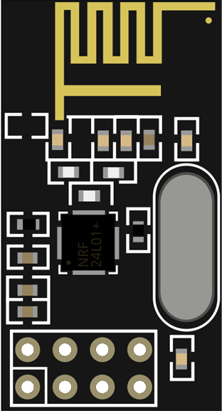
Pin Configuration and Descriptions

Pin Number Name Description
1 GND Ground
2 VCC Power supply (1.9 to 3.6V)
3 CE Chip Enable (activates RX or TX mode)
4 CSN Chip Select Not (SPI chip select)
5 SCK Serial Clock (SPI clock)
6 MOSI Master Out Slave In (SPI data input to NRF24L01)
7 MISO Master In Slave Out (SPI data output from NRF24L01)
8 IRQ Interrupt Request (active low, maskable interrupt signal)

Usage Instructions

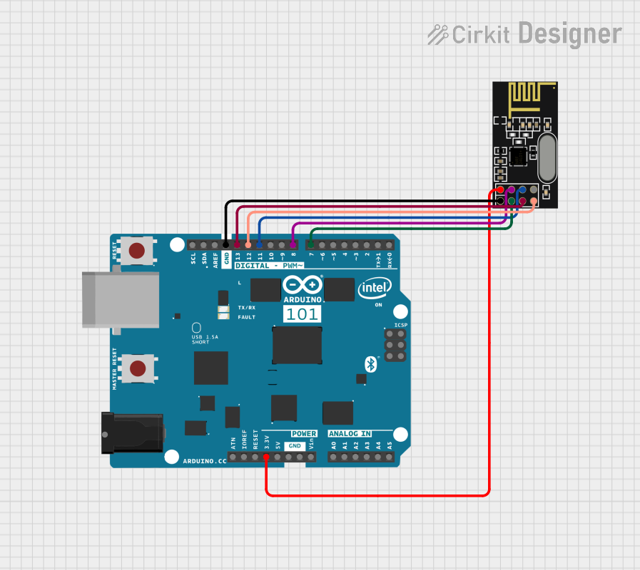
How to Use the Component in a Circuit

  1. Power Supply: Connect the VCC pin to a 1.9 to 3.6V power supply and the GND pin to the ground.
  2. SPI Interface: Connect the SCK, MOSI, MISO, and CSN pins to the corresponding SPI pins on your microcontroller.
  3. Chip Enable: The CE pin is used to switch between the RX and TX modes. Connect it to a GPIO pin on your microcontroller.
  4. Interrupts (Optional): The IRQ pin can be connected to an interrupt-capable GPIO pin on your microcontroller to handle events like data reception, transmission completion, and more.

Important Considerations and Best Practices

  • Ensure that the power supply is clean and within the specified voltage range to prevent damage.
  • Use bypass capacitors (typically 0.1uF and 10uF) near the power supply pins to filter out noise.
  • Keep the antenna area of the NRF24L01 module clear of metal components to avoid interference.
  • When designing the PCB, ensure that the trace lengths for the SPI signals are kept as short as possible to reduce signal degradation.
  • For better range and reliability, consider using an NRF24L01 module with an external antenna.

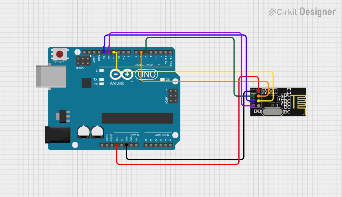
Example Code for Arduino UNO

#include <SPI.h>
#include "RF24.h"

// Create an RF24 object
RF24 radio(9, 10); // CE, CSN pins

void setup() {
  // Initialize the NRF24L01 module
  radio.begin();
  
  // Set the PA Level (transmit power)
  radio.setPALevel(RF24_PA_LOW);
  
  // Open a writing and reading pipe on each radio, with unique addresses
  radio.openWritingPipe(0xF0F0F0F0E1LL);
  radio.openReadingPipe(1, 0xF0F0F0F0D2LL);
  
  // Start the radio listening for data
  radio.startListening();
}

void loop() {
  if (radio.available()) {
    char text[32] = {0};
    radio.read(&text, sizeof(text));
    Serial.println(text);
  }
}

Troubleshooting and FAQs

Common Issues

  • Range is too short or unstable: Ensure there are no obstructions or metal surfaces near the antenna. Also, check the power supply and antenna connections.
  • No communication between modules: Verify that the SPI connections are correct and that the modules have matching addresses and settings.
  • Module not responding: Check the power supply voltage and connections. Ensure that the module is correctly initialized in your code.

Solutions and Tips for Troubleshooting

  • Use the printDetails() function provided by the RF24 library to check the configuration of the NRF24L01 module.
  • Ensure that the ground of the NRF24L01 module is well connected to the ground of the microcontroller.
  • When using multiple modules, ensure that each has a unique address.
  • If using the IRQ pin, ensure that the interrupt service routine is correctly configured and not too lengthy.

FAQs

Q: Can I use the NRF24L01 with a 5V microcontroller like Arduino UNO? A: Yes, but you will need to use a level shifter or voltage divider for the SPI lines, as the NRF24L01 operates at a maximum of 3.6V.

Q: How many NRF24L01 modules can communicate with each other? A: The NRF24L01 can have up to 6 receiver addresses, allowing one transmitter to communicate with up to 6 receivers in a star network topology.

Q: Can the NRF24L01 module transmit and receive at the same time? A: No, the NRF24L01 cannot transmit and receive simultaneously as it is not a full-duplex device. It can be quickly switched between transmission and reception modes, though.

Q: What is the maximum data rate of the NRF24L01? A: The NRF24L01 supports data rates of 250kbps, 1Mbps, and 2Mbps. The data rate can be configured using the setDataRate() function of the RF24 library.