How to Use GPIO pin header for Jetson Orin Nano: Examples, Pinouts, and Specs
Introduction
The GPIO pin header (J41) is a General Purpose Input/Output interface designed by Nvidia for the Jetson Orin Nano. This 40-pin header provides a versatile way to connect external devices, sensors, and modules to the Jetson Orin Nano, enabling input and output operations for a wide range of applications. It is compatible with standard GPIO peripherals and supports various communication protocols such as I2C, UART, and SPI.
Explore Projects Built with GPIO pin header for Jetson Orin Nano
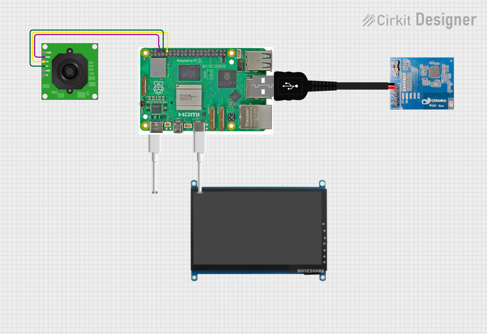
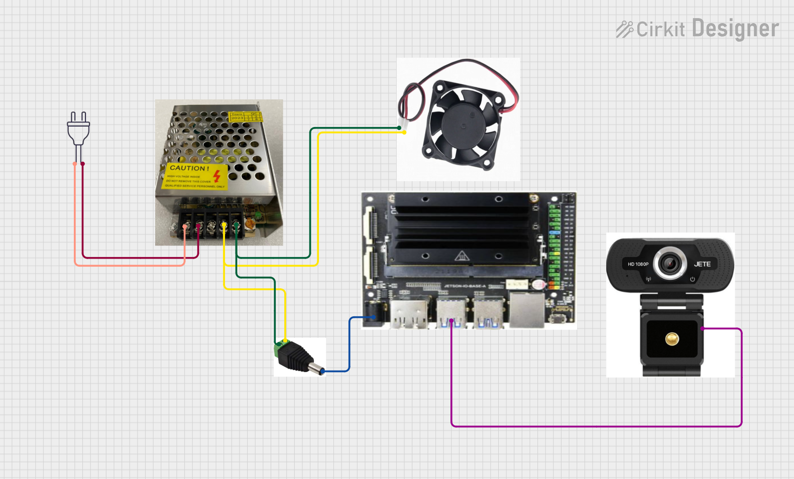
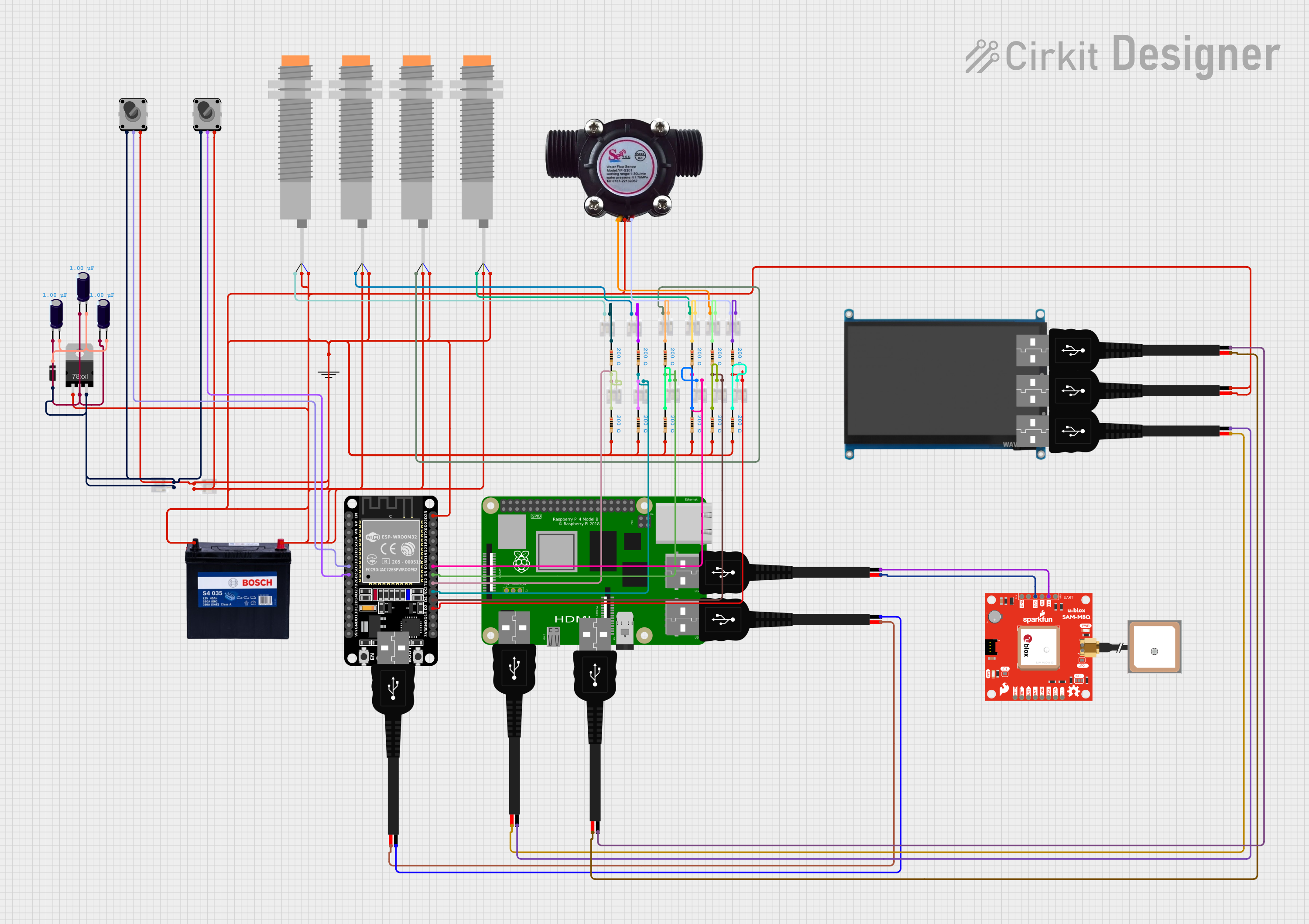

Explore Projects Built with GPIO pin header for Jetson Orin Nano
Common Applications and Use Cases
- Connecting sensors (e.g., temperature, motion, light sensors)
- Driving actuators (e.g., motors, relays, LEDs)
- Interfacing with external microcontrollers or development boards
- Prototyping IoT and robotics projects
- Implementing custom hardware extensions
Technical Specifications
Key Technical Details
- Manufacturer: Nvidia
- Part ID: J41
- Number of Pins: 40 (2x20 configuration)
- Voltage Levels: 3.3V logic (5V-tolerant on some pins)
- Communication Protocols Supported: GPIO, I2C, UART, SPI, PWM
- Power Pins: 5V and 3.3V power supply available
- Ground Pins: Multiple GND pins for stable connections
Pin Configuration and Descriptions
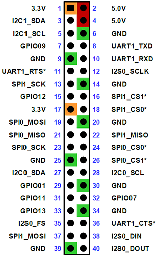
The J41 GPIO pin header follows a 40-pin layout, similar to the Raspberry Pi GPIO header. Below is the pinout table:
| Pin Number | Pin Name | Function/Description | Voltage Level |
|---|---|---|---|
| 1 | 3.3V | Power Supply (3.3V) | 3.3V |
| 2 | 5V | Power Supply (5V) | 5V |
| 3 | I2C SDA | I2C Data Line | 3.3V |
| 4 | 5V | Power Supply (5V) | 5V |
| 5 | I2C SCL | I2C Clock Line | 3.3V |
| 6 | GND | Ground | 0V |
| 7 | GPIO4 | General Purpose I/O | 3.3V |
| 8 | UART TXD | UART Transmit | 3.3V |
| 9 | GND | Ground | 0V |
| 10 | UART RXD | UART Receive | 3.3V |
| ... | ... | ... | ... |
| 39 | GND | Ground | 0V |
| 40 | GPIO21 | General Purpose I/O | 3.3V |
Note: For the complete pinout and advanced configurations, refer to the official Nvidia Jetson Orin Nano documentation.
Usage Instructions
How to Use the GPIO Pin Header in a Circuit
- Identify the Pins: Refer to the pinout table above to locate the required pins for your application (e.g., GPIO, power, ground, or communication lines).
- Connect External Devices: Use jumper wires or a compatible GPIO breakout board to connect sensors, actuators, or other peripherals to the J41 header.
- Configure GPIO Pins: Use the Jetson GPIO library or other software tools to configure the pins as input or output, depending on your application.
- Power the Board: Ensure the Jetson Orin Nano is powered on and connected to a stable power source.
- Test the Circuit: Verify the connections and functionality of the external devices using test scripts or diagnostic tools.
Important Considerations and Best Practices
- Voltage Compatibility: Ensure that connected devices operate at 3.3V logic levels. While some pins are 5V-tolerant, exceeding voltage limits may damage the board.
- Pin Protection: Avoid short circuits or overloading the GPIO pins. Use resistors or level shifters if necessary.
- Static Discharge: Handle the board and connected components with care to prevent electrostatic discharge (ESD) damage.
- Software Libraries: Use the official Jetson GPIO Python library for easy pin configuration and control.
Example: Blinking an LED with GPIO
Below is an example Python script to blink an LED connected to GPIO pin 7 (physical pin 7) using the Jetson GPIO library:
import Jetson.GPIO as GPIO  # Import the Jetson GPIO library
import time                 # Import the time library for delays
Pin Definitions
led_pin = 7 # Physical pin 7 (GPIO4)
Pin Setup
GPIO.setmode(GPIO.BOARD) # Use physical pin numbering GPIO.setup(led_pin, GPIO.OUT) # Set pin as an output pin
print("Press Ctrl+C to exit") try: while True: GPIO.output(led_pin, GPIO.HIGH) # Turn LED on time.sleep(1) # Wait for 1 second GPIO.output(led_pin, GPIO.LOW) # Turn LED off time.sleep(1) # Wait for 1 second except KeyboardInterrupt: print("Exiting program")
Cleanup
GPIO.cleanup() # Reset GPIO settings
> **Note**: Ensure the LED is connected in series with a current-limiting resistor (e.g., 330Ω) to prevent damage.
Troubleshooting and FAQs
Common Issues Users Might Face
GPIO Pin Not Responding:
- Cause: Incorrect pin configuration or software setup.
- Solution: Double-check the pin number and ensure the pin is configured correctly in the software.
Device Not Detected:
- Cause: Loose connections or incorrect wiring.
- Solution: Verify all connections and ensure the device is powered properly.
Overheating or Damage:
- Cause: Exceeding voltage/current limits or short circuits.
- Solution: Use appropriate resistors, level shifters, and avoid overloading the pins.
Library Import Errors:
- Cause: Missing or outdated Jetson GPIO library.
- Solution: Install or update the library using the following command:
sudo apt-get install python3-jetson-gpio
FAQs
Q: Can I use 5V devices directly with the GPIO pins?
A: No, the GPIO pins operate at 3.3V logic levels. Use a level shifter for 5V devices.Q: How do I enable I2C or SPI on the J41 header?
A: These interfaces are enabled via the Jetson device tree. Refer to Nvidia's documentation for detailed instructions.Q: Is the J41 header compatible with Raspberry Pi HATs?
A: The pin layout is similar, but compatibility depends on the specific HAT and its power/voltage requirements.Q: Can I power the Jetson Orin Nano through the J41 header?
A: No, the J41 header provides power output but is not designed for powering the board itself. Use the dedicated power input for the Jetson Orin Nano.
For additional support, consult the official Nvidia Jetson Orin Nano documentation or community forums.