How to Use STM8S103F3P6: Examples, Pinouts, and Specs
Introduction
The STM8S103F3P6 is a low-power 8-bit microcontroller manufactured by STMicroelectronics. It features an 8-bit CPU core, up to 8 KB of Flash memory, and a variety of integrated peripherals, making it a versatile choice for embedded applications. This microcontroller is designed for cost-sensitive applications while maintaining high performance and reliability.
Explore Projects Built with STM8S103F3P6


Explore Projects Built with STM8S103F3P6
Common Applications and Use Cases
- Home automation systems
- Industrial control systems
- Consumer electronics
- Motor control applications
- IoT devices and sensors
- Educational and prototyping projects
Technical Specifications
The STM8S103F3P6 microcontroller offers a robust set of features suitable for a wide range of applications. Below are its key technical specifications:
Key Features
- Core: STM8 8-bit CPU
- Flash Memory: 8 KB
- RAM: 1 KB
- EEPROM: 640 bytes
- Operating Voltage: 2.95V to 5.5V
- Clock Speed: Up to 16 MHz
- I/O Pins: 16 GPIO pins
- Communication Interfaces: UART, SPI, I²C
- Timers: 3 timers (16-bit and 8-bit)
- ADC: 10-bit ADC with up to 5 channels
- Power Consumption: Low-power modes available
- Package: TSSOP-20
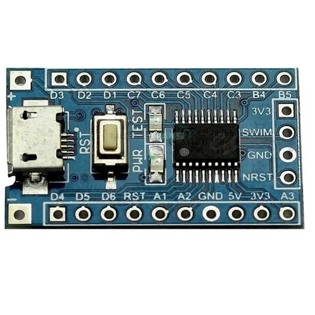
Pin Configuration and Descriptions
The STM8S103F3P6 is available in a 20-pin TSSOP package. Below is the pinout and description:
| Pin Number | Pin Name | Function | Description |
|---|---|---|---|
| 1 | NRST | Reset | Active-low reset input |
| 2 | VSS | Ground | Ground connection |
| 3 | VDD | Power Supply | Positive power supply (2.95V to 5.5V) |
| 4 | PA1 | GPIO / ADC_IN1 | General-purpose I/O or ADC channel 1 |
| 5 | PA2 | GPIO / ADC_IN2 | General-purpose I/O or ADC channel 2 |
| 6 | PA3 | GPIO / ADC_IN3 | General-purpose I/O or ADC channel 3 |
| 7 | PA4 | GPIO / ADC_IN4 | General-purpose I/O or ADC channel 4 |
| 8 | PA5 | GPIO / ADC_IN5 | General-purpose I/O or ADC channel 5 |
| 9 | PB4 | GPIO / I²C_SCL | General-purpose I/O or I²C clock line |
| 10 | PB5 | GPIO / I²C_SDA | General-purpose I/O or I²C data line |
| 11 | PB6 | GPIO / UART_TX | General-purpose I/O or UART transmit |
| 12 | PB7 | GPIO / UART_RX | General-purpose I/O or UART receive |
| 13 | PC3 | GPIO | General-purpose I/O |
| 14 | PC4 | GPIO | General-purpose I/O |
| 15 | PC5 | GPIO | General-purpose I/O |
| 16 | PC6 | GPIO | General-purpose I/O |
| 17 | PC7 | GPIO | General-purpose I/O |
| 18 | PD1 | GPIO | General-purpose I/O |
| 19 | PD2 | GPIO | General-purpose I/O |
| 20 | PD3 | GPIO | General-purpose I/O |
Usage Instructions
The STM8S103F3P6 is a versatile microcontroller that can be used in a variety of embedded systems. Below are the steps and considerations for using this component effectively.
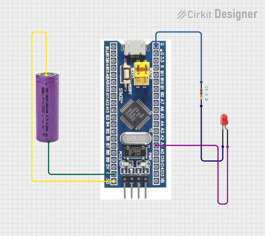
How to Use the STM8S103F3P6 in a Circuit
- Power Supply: Connect the VDD pin to a regulated power source (2.95V to 5.5V) and the VSS pin to ground.
- Reset: Use the NRST pin for resetting the microcontroller. Connect it to a pull-up resistor (typically 10 kΩ) to VDD.
- Clock Configuration: The microcontroller can use an internal RC oscillator or an external crystal oscillator. For precise timing, connect an external crystal to the appropriate pins.
- Programming: Use the SWIM (Single Wire Interface Module) pin for programming and debugging. A compatible ST-Link programmer is required.
- GPIO Configuration: Configure the GPIO pins as input, output, or alternate function using the microcontroller's firmware.
- Peripherals: Utilize the UART, SPI, I²C, ADC, and timers as needed for your application.
Important Considerations and Best Practices
- Decoupling Capacitors: Place a 0.1 µF ceramic capacitor close to the VDD pin to reduce noise and stabilize the power supply.
- Pull-up Resistors: Use pull-up resistors on unused pins to prevent floating inputs.
- Programming Voltage: Ensure the programming voltage matches the microcontroller's operating voltage.
- Low-Power Modes: Use the low-power modes to reduce power consumption in battery-operated applications.
Example: Connecting to an Arduino UNO
The STM8S103F3P6 can communicate with an Arduino UNO via UART. Below is an example Arduino sketch to send data to the STM8S103F3P6:
// Arduino UNO UART Communication with STM8S103F3P6
// Connect Arduino TX (Pin 1) to STM8 RX (PB7)
// Connect Arduino RX (Pin 0) to STM8 TX (PB6)
// Ensure both devices share a common ground

void setup() {
  Serial.begin(9600); // Initialize UART at 9600 baud rate
}

void loop() {
  Serial.println("Hello, STM8!"); // Send data to STM8
  delay(1000); // Wait for 1 second
}
Troubleshooting and FAQs
Common Issues and Solutions
Microcontroller Not Responding
- Cause: Incorrect power supply or missing decoupling capacitor.
- Solution: Verify the power supply voltage and add a 0.1 µF capacitor near the VDD pin.
Programming Failure
- Cause: Incorrect SWIM connection or incompatible programmer.
- Solution: Check the SWIM pin connection and use an ST-Link programmer.
Unstable Operation
- Cause: Noise on the power supply or floating input pins.
- Solution: Add decoupling capacitors and pull-up resistors to unused pins.
UART Communication Issues
- Cause: Mismatched baud rate or incorrect wiring.
- Solution: Ensure the baud rate matches on both devices and verify the TX/RX connections.
FAQs
Q: Can the STM8S103F3P6 operate at 3.3V?
A: Yes, the microcontroller can operate within a voltage range of 2.95V to 5.5V.
Q: What is the maximum clock speed of the STM8S103F3P6?
A: The maximum clock speed is 16 MHz.
Q: How do I program the STM8S103F3P6?
A: Use the SWIM interface with an ST-Link programmer and the ST Visual Programmer (STVP) software.
Q: Does the STM8S103F3P6 support low-power modes?
A: Yes, it supports multiple low-power modes for energy-efficient applications.