How to Use LED Driver: Examples, Pinouts, and Specs
Introduction
An LED driver is an electronic device designed to regulate the power supplied to an LED or a string of LEDs. It ensures that the LEDs receive the correct voltage and current, which is critical for their optimal performance, efficiency, and longevity. LED drivers are essential for preventing issues such as overheating, flickering, or premature failure of LEDs.
Explore Projects Built with LED Driver
Explore Projects Built with LED Driver
Common Applications and Use Cases
- Lighting Systems: Used in residential, commercial, and industrial LED lighting.
- Display Panels: Powers LEDs in digital signage and display boards.
- Automotive Lighting: Ensures stable operation of LED headlights and taillights.
- Backlighting: Provides power to LEDs in LCD screens and monitors.
- Architectural Lighting: Supports decorative and functional lighting installations.
Technical Specifications
Below are the general technical specifications for a typical LED driver. Note that specific models may vary, so always refer to the datasheet of the particular driver you are using.
Key Technical Details
- Input Voltage: 90V to 265V AC (or 12V to 48V DC for low-voltage drivers)
- Output Voltage: 2V to 48V DC (depending on the LED configuration)
- Output Current: 350mA to 1500mA (constant current)
- Power Rating: 1W to 100W (varies by model)
- Efficiency: Up to 90%
- Dimming Support: PWM, 0-10V, or TRIAC dimming (optional)
- Protection Features: Overvoltage, overcurrent, short-circuit, and thermal protection
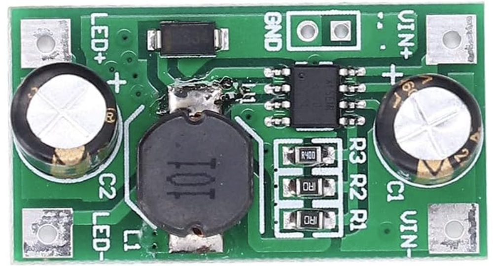
Pin Configuration and Descriptions
The pin configuration of an LED driver depends on its type (e.g., constant current or constant voltage). Below is a general example for a constant current LED driver:
| Pin Name | Description |
|---|---|
| VIN+ | Positive input voltage terminal (connect to the power source). |
| VIN- | Negative input voltage terminal (connect to the power source ground). |
| LED+ | Positive output terminal (connect to the anode of the LED or LED string). |
| LED- | Negative output terminal (connect to the cathode of the LED or LED string). |
| DIM | Dimming control input (optional, used for brightness adjustment). |
Usage Instructions
How to Use the Component in a Circuit
- Determine the LED Requirements: Identify the voltage and current requirements of your LED or LED string.
- Select the Appropriate Driver: Choose an LED driver that matches the voltage and current specifications of your LEDs.
- Connect the Input:
- For AC-powered drivers, connect the VIN+ and VIN- terminals to the AC power source.
- For DC-powered drivers, connect the VIN+ and VIN- terminals to the DC power source.
- Connect the Output:
- Connect the LED+ terminal to the anode (positive terminal) of the LED or LED string.
- Connect the LED- terminal to the cathode (negative terminal) of the LED or LED string.
- Optional Dimming: If the driver supports dimming, connect the DIM pin to a compatible dimming controller or signal source.
- Power On: Turn on the power source and verify that the LEDs light up as expected.
Important Considerations and Best Practices
- Match Voltage and Current: Always ensure the driver’s output voltage and current match the LED specifications.
- Heat Management: Use proper heat sinks or cooling mechanisms to prevent overheating of the LEDs and the driver.
- Polarity: Double-check the polarity of all connections to avoid damage to the LEDs or the driver.
- Dimming Compatibility: If using dimming, ensure the dimming method (e.g., PWM or 0-10V) is compatible with the driver.
- Environmental Conditions: Use drivers rated for the operating temperature and humidity of your application.
Example: Using an LED Driver with Arduino UNO
If your LED driver supports PWM dimming, you can control the brightness of the LEDs using an Arduino UNO. Below is an example code:
// Example: Controlling LED brightness with Arduino and PWM dimming
// Connect the DIM pin of the LED driver to pin 9 of the Arduino UNO

int dimmingPin = 9; // PWM pin connected to the DIM pin of the LED driver
int brightness = 0; // Initial brightness level (0-255)

void setup() {
  pinMode(dimmingPin, OUTPUT); // Set the dimming pin as an output
}

void loop() {
  // Gradually increase brightness
  for (brightness = 0; brightness <= 255; brightness++) {
    analogWrite(dimmingPin, brightness); // Write PWM signal to DIM pin
    delay(10); // Small delay for smooth transition
  }

  // Gradually decrease brightness
  for (brightness = 255; brightness >= 0; brightness--) {
    analogWrite(dimmingPin, brightness); // Write PWM signal to DIM pin
    delay(10); // Small delay for smooth transition
  }
}
Troubleshooting and FAQs
Common Issues and Solutions
LEDs Do Not Light Up:
- Cause: Incorrect wiring or insufficient power supply.
- Solution: Verify all connections and ensure the power supply meets the driver’s input requirements.
LEDs Flicker:
- Cause: Incompatible dimming signal or unstable power supply.
- Solution: Check the dimming signal type and ensure the power supply is stable.
Driver Overheats:
- Cause: Overloading or poor ventilation.
- Solution: Ensure the driver is not powering more LEDs than its rated capacity and improve ventilation.
Dimming Does Not Work:
- Cause: Incorrect dimming connection or incompatible dimming method.
- Solution: Verify the dimming connection and ensure the dimming method matches the driver’s specifications.
FAQs
Can I use an LED driver with non-LED loads? No, LED drivers are specifically designed for LEDs and may not work properly with other types of loads.
What happens if I exceed the driver’s rated current? Exceeding the rated current can cause the driver to overheat, shut down, or fail. Always use a driver with sufficient current capacity.
Can I connect multiple LED drivers in parallel? It is not recommended to connect LED drivers in parallel, as it can lead to uneven current distribution and potential damage.
How do I choose between constant current and constant voltage drivers? Use a constant current driver for LEDs that require a specific current and a constant voltage driver for LEDs with built-in current regulation. Always check the LED specifications.