
How to Use 4R7 Voltage Regulator: Examples, Pinouts, and Specs
 Design with 4R7 Voltage Regulator in Cirkit Designer
Introduction
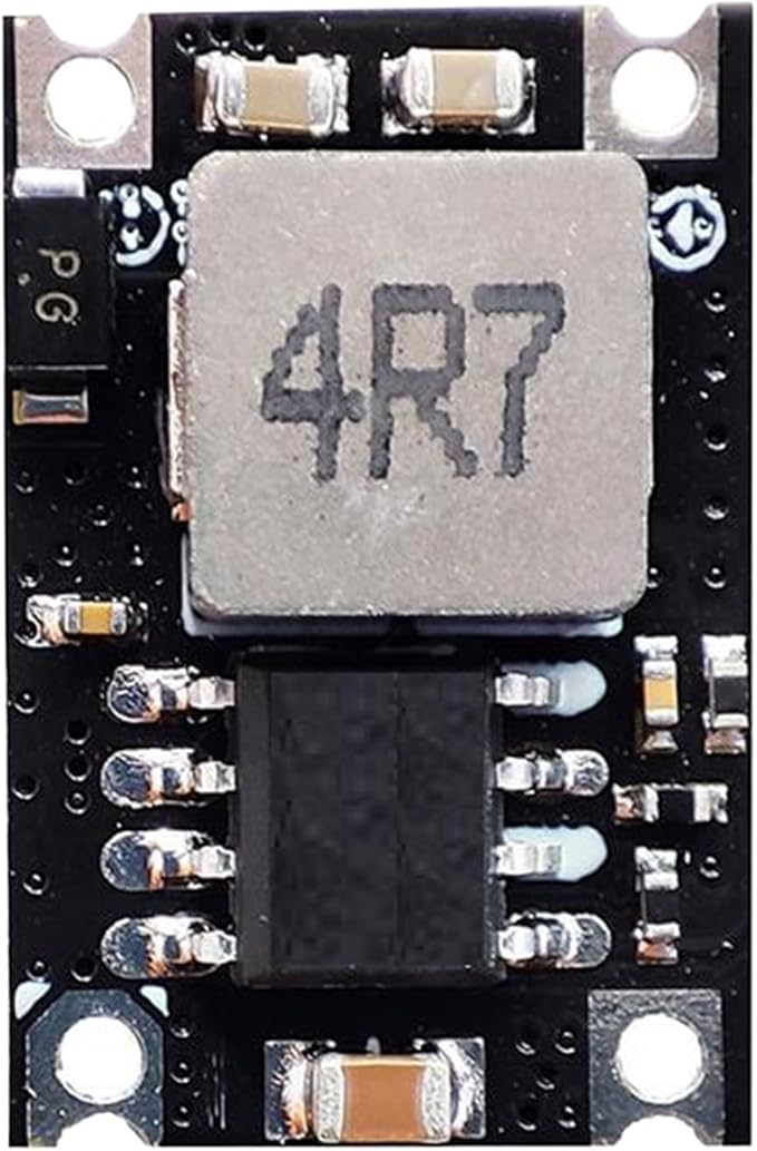
The 4R7 Voltage Regulator is a compact and efficient electronic component designed to maintain a constant output voltage of 4.7 volts. It ensures a stable power supply to sensitive electronic circuits, protecting them from voltage fluctuations and ensuring reliable operation. This regulator is commonly used in low-power applications, such as microcontroller-based systems, sensors, and portable devices.
Explore Projects Built with 4R7 Voltage Regulator
 Open Project in Cirkit Designer
 Open Project in Cirkit Designer
 Open Project in Cirkit Designer
 Open Project in Cirkit Designer
Explore Projects Built with 4R7 Voltage Regulator
Open Project in Cirkit DesignerOpen Project in Cirkit DesignerOpen Project in Cirkit DesignerOpen Project in Cirkit DesignerCommon Applications and Use Cases
- Powering microcontrollers (e.g., Arduino, ESP32, etc.)
- Stabilizing voltage for sensors and modules
- Battery-powered devices requiring a fixed 4.7V output
- Noise-sensitive analog circuits
Technical Specifications
The following table outlines the key technical details of the 4R7 Voltage Regulator:
| Parameter | Value |
|---|---|
| Output Voltage | 4.7V ± 2% |
| Input Voltage Range | 6V to 20V |
| Maximum Output Current | 1A |
| Dropout Voltage | 1.1V (typical) |
| Quiescent Current | 5mA (typical) |
| Operating Temperature | -40°C to +125°C |
| Package Type | TO-220, SOT-223, or similar |
Pin Configuration and Descriptions
The 4R7 Voltage Regulator typically has three pins. The pinout is as follows:
| Pin | Name | Description |
|---|---|---|
| 1 | Input (VIN) | Connect to the unregulated input voltage source. |
| 2 | Ground (GND) | Connect to the circuit ground. |
| 3 | Output (VOUT) | Provides the regulated 4.7V output voltage. |
Usage Instructions
How to Use the 4R7 Voltage Regulator in a Circuit
- Input Voltage: Ensure the input voltage (VIN) is at least 6V and does not exceed 20V. A higher input voltage may damage the regulator.
- Capacitors: Connect capacitors to stabilize the input and output voltages:
- Place a 0.33µF ceramic capacitor between VIN and GND.
- Place a 0.1µF ceramic capacitor between VOUT and GND.
- Connections:
- Connect the unregulated power source to the VIN pin.
- Connect the GND pin to the circuit ground.
- Connect the VOUT pin to the load requiring a 4.7V supply.
- Heat Dissipation: If the regulator is supplying high current (close to 1A), attach a heatsink to prevent overheating.
Example Circuit
Below is a simple circuit diagram for using the 4R7 Voltage Regulator:
Unregulated Power Source (+) ---- VIN (Pin 1)
Unregulated Power Source (-) ---- GND (Pin 2)
VOUT (Pin 3) -------------------- Load (+)
GND (Pin 2) --------------------- Load (-)
Using the 4R7 Voltage Regulator with Arduino UNO
The 4R7 Voltage Regulator can be used to power an Arduino UNO by providing a stable 4.7V supply to its 5V pin. Below is an example Arduino code to blink an LED when powered by the 4R7 regulator:
// Simple LED Blink Example
// This code assumes the Arduino UNO is powered by the 4R7 Voltage Regulator.

const int ledPin = 13; // Built-in LED pin on Arduino UNO

void setup() {
  pinMode(ledPin, OUTPUT); // Set the LED pin as an output
}

void loop() {
  digitalWrite(ledPin, HIGH); // Turn the LED on
  delay(1000);                // Wait for 1 second
  digitalWrite(ledPin, LOW);  // Turn the LED off
  delay(1000);                // Wait for 1 second
}
Important Considerations and Best Practices
- Input Voltage Range: Always ensure the input voltage is within the specified range (6V to 20V).
- Heat Management: Use a heatsink if the regulator is operating near its maximum current rating.
- Capacitor Placement: Place the input and output capacitors as close to the regulator pins as possible to minimize noise and instability.
- Load Current: Do not exceed the maximum output current of 1A to avoid damaging the regulator.
Troubleshooting and FAQs
Common Issues and Solutions
Output Voltage is Incorrect:
- Check the input voltage. Ensure it is at least 6V.
- Verify the capacitors are correctly connected and of the recommended values.
- Ensure the load does not exceed the maximum current rating.
Regulator Overheating:
- Attach a heatsink to the regulator.
- Reduce the load current or input voltage if possible.
No Output Voltage:
- Verify all connections, especially VIN and GND.
- Check for short circuits or damaged components.
Noise or Instability in Output Voltage:
- Ensure the input and output capacitors are placed close to the regulator pins.
- Use low-ESR capacitors for better performance.
FAQs
Q: Can I use the 4R7 Voltage Regulator with a 5V input?
A: No, the input voltage must be at least 6V to ensure proper regulation.
Q: What happens if I exceed the maximum current rating?
A: Exceeding the 1A current rating may cause the regulator to overheat or shut down to protect itself.
Q: Can I use the 4R7 Voltage Regulator without capacitors?
A: While it may work in some cases, it is highly recommended to use the specified capacitors to ensure stable operation and prevent oscillations.
Q: Is the 4R7 Voltage Regulator suitable for battery-powered devices?
A: Yes, it is commonly used in battery-powered devices, provided the input voltage is within the specified range.