
How to Use NEMA 23 Closed Loop Stepper System: Examples, Pinouts, and Specs
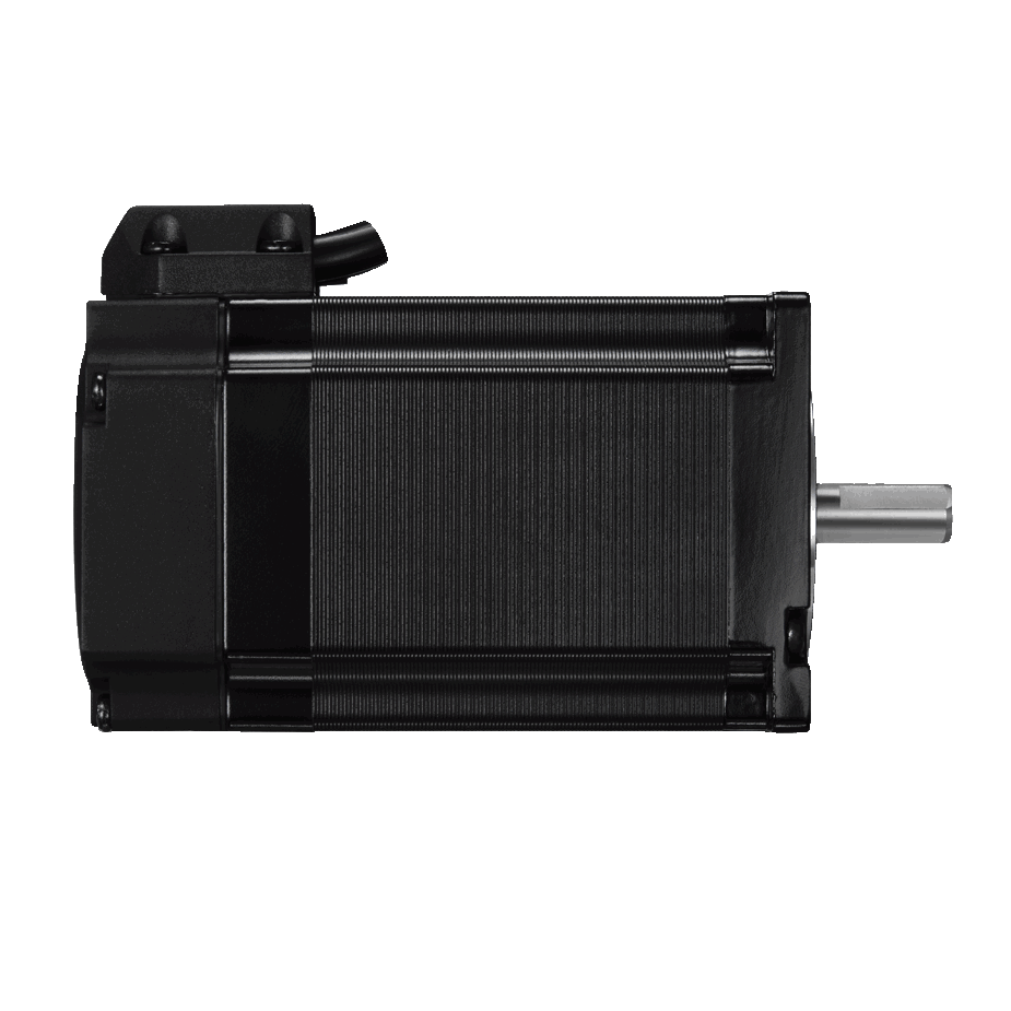
 Design with NEMA 23 Closed Loop Stepper System in Cirkit Designer
Introduction
The NEMA 23 Closed Loop Stepper System (Leadshine CS-M22323) is a high-performance stepper motor system designed for precision motion control applications. Unlike traditional open-loop stepper motors, this system incorporates closed-loop control, which significantly enhances accuracy, reduces vibration, and improves torque performance. The system is ideal for applications requiring reliable and efficient motion control, such as CNC machines, 3D printers, robotics, and automated manufacturing systems.
Explore Projects Built with NEMA 23 Closed Loop Stepper System
 Open Project in Cirkit Designer
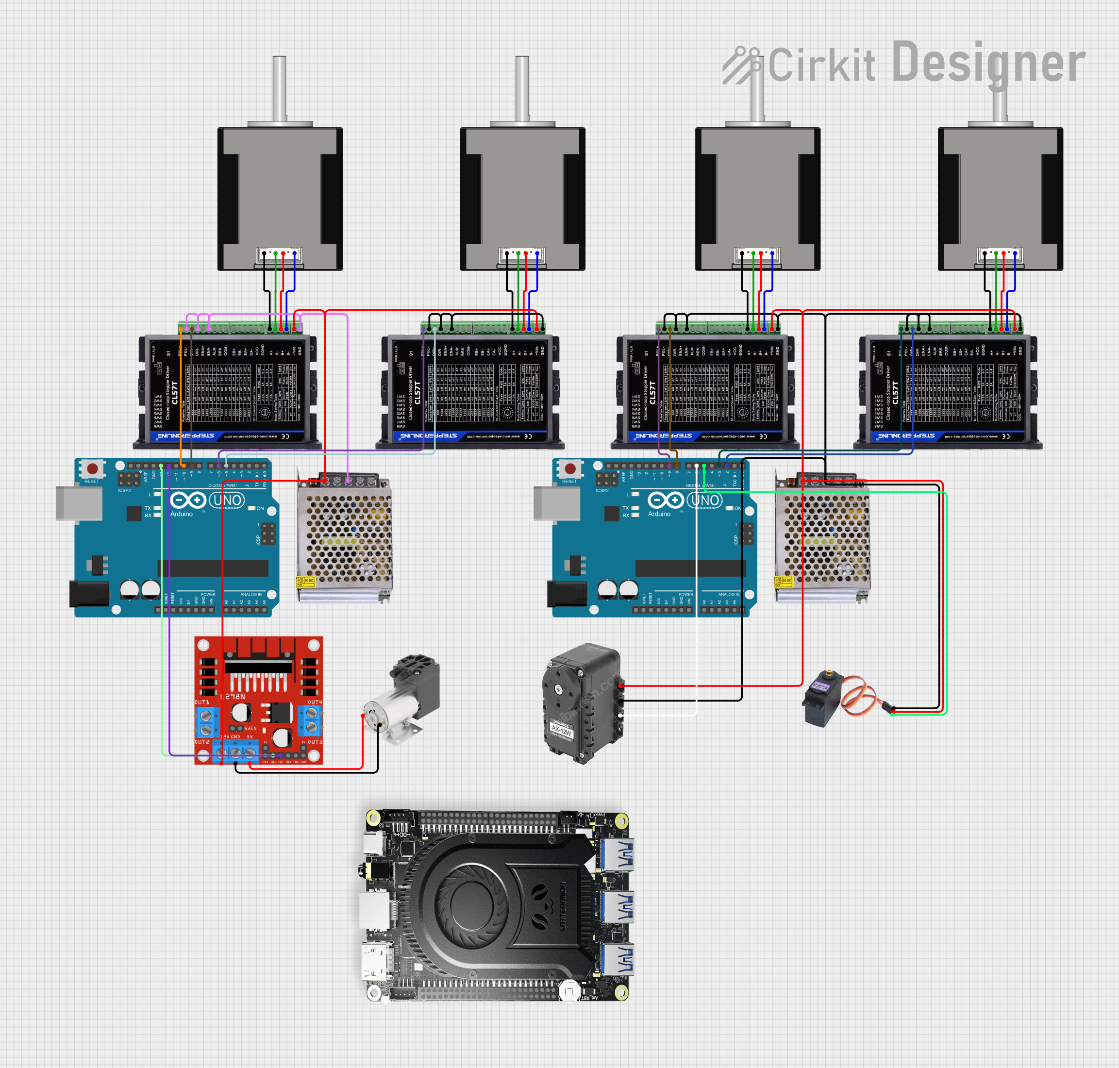 Open Project in Cirkit Designer
 Open Project in Cirkit Designer
 Open Project in Cirkit Designer
Explore Projects Built with NEMA 23 Closed Loop Stepper System
Open Project in Cirkit DesignerOpen Project in Cirkit DesignerOpen Project in Cirkit DesignerOpen Project in Cirkit DesignerCommon Applications
- CNC machines for milling, cutting, and engraving
- Robotics for precise motion and positioning
- 3D printers for accurate layer deposition
- Conveyor systems in automated manufacturing
- Medical devices requiring precise motor control
Technical Specifications
Key Technical Details
| Parameter | Specification |
|---|---|
| Motor Frame Size | NEMA 23 (57 x 57 mm) |
| Step Angle | 1.8° |
| Holding Torque | 2.3 Nm |
| Rated Current | 3.5 A |
| Power Supply Voltage | 24-50 VDC |
| Encoder Resolution | 1000 lines/rev (4000 counts/rev) |
| Communication Interface | Pulse/Direction or RS232/RS485 |
| Operating Temperature | -20°C to +50°C |
| Insulation Class | Class B |
Pin Configuration and Descriptions
Motor Connector (4-pin)
| Pin Number | Name | Description |
|---|---|---|
| 1 | A+ | Phase A positive |
| 2 | A- | Phase A negative |
| 3 | B+ | Phase B positive |
| 4 | B- | Phase B negative |
Encoder Connector (6-pin)
| Pin Number | Name | Description |
|---|---|---|
| 1 | VCC | Power supply for encoder (5V) |
| 2 | GND | Ground |
| 3 | A+ | Encoder A channel positive |
| 4 | A- | Encoder A channel negative |
| 5 | B+ | Encoder B channel positive |
| 6 | B- | Encoder B channel negative |
Control Signal Connector (8-pin)
| Pin Number | Name | Description |
|---|---|---|
| 1 | PUL+ | Pulse signal positive |
| 2 | PUL- | Pulse signal negative |
| 3 | DIR+ | Direction signal positive |
| 4 | DIR- | Direction signal negative |
| 5 | ENA+ | Enable signal positive |
| 6 | ENA- | Enable signal negative |
| 7 | ALM+ | Alarm signal positive |
| 8 | ALM- | Alarm signal negative |
Usage Instructions
How to Use the Component in a Circuit
- Power Supply: Connect a DC power supply (24-50 VDC) to the motor driver. Ensure the power supply can provide sufficient current for the motor's rated current (3.5 A).
- Motor Connection: Wire the motor's 4-phase wires (A+, A-, B+, B-) to the corresponding terminals on the driver.
- Encoder Connection: Connect the encoder's 6-pin output to the driver to enable closed-loop feedback.
- Control Signals: Use the control signal connector to interface with a microcontroller or CNC controller. For example:
- Connect
PUL+andPUL-to the pulse output of the controller. - Connect
DIR+andDIR-to the direction output of the controller. - Optionally, connect
ENA+andENA-to enable or disable the motor.
- Connect
Important Considerations
- Power Supply Selection: Use a regulated DC power supply within the specified voltage range. Avoid exceeding the maximum voltage to prevent damage.
- Heat Dissipation: Ensure proper ventilation or use a heatsink to manage heat generated by the motor and driver.
- Signal Noise: Use shielded cables for control signals to minimize electromagnetic interference (EMI).
- Mounting: Securely mount the motor to prevent vibration or misalignment during operation.
Example: Connecting to an Arduino UNO
Below is an example of how to control the NEMA 23 Closed Loop Stepper System using an Arduino UNO.
Circuit Diagram
- Connect
PUL+to Arduino pin 3 andPUL-to GND. - Connect
DIR+to Arduino pin 4 andDIR-to GND. - Connect
ENA+to Arduino pin 5 andENA-to GND.
Arduino Code
// Define control pins
#define PUL_PIN 3  // Pulse signal pin
#define DIR_PIN 4  // Direction signal pin
#define ENA_PIN 5  // Enable signal pin

void setup() {
  // Set pins as outputs
  pinMode(PUL_PIN, OUTPUT);
  pinMode(DIR_PIN, OUTPUT);
  pinMode(ENA_PIN, OUTPUT);

  // Enable the motor
  digitalWrite(ENA_PIN, LOW); // LOW to enable motor
}

void loop() {
  // Set direction
  digitalWrite(DIR_PIN, HIGH); // HIGH for clockwise, LOW for counterclockwise

  // Generate pulses to move the motor
  for (int i = 0; i < 200; i++) { // 200 steps for one revolution
    digitalWrite(PUL_PIN, HIGH);
    delayMicroseconds(500); // Adjust for speed
    digitalWrite(PUL_PIN, LOW);
    delayMicroseconds(500);
  }

  delay(1000); // Wait for 1 second before reversing direction

  // Reverse direction
  digitalWrite(DIR_PIN, LOW);

  // Generate pulses to move the motor in the opposite direction
  for (int i = 0; i < 200; i++) {
    digitalWrite(PUL_PIN, HIGH);
    delayMicroseconds(500);
    digitalWrite(PUL_PIN, LOW);
    delayMicroseconds(500);
  }

  delay(1000); // Wait for 1 second before repeating
}
Troubleshooting and FAQs
Common Issues and Solutions
Motor Not Moving:
- Verify the power supply voltage and current are within the specified range.
- Check all wiring connections, especially the control signals.
- Ensure the enable signal (
ENA+andENA-) is properly configured.
Erratic or Inconsistent Movement:
- Check for loose or damaged wires.
- Use shielded cables to reduce signal noise.
- Verify the pulse and direction signals are correctly timed.
Overheating:
- Ensure proper ventilation or use a heatsink.
- Reduce the motor's current setting if possible.
Encoder Feedback Errors:
- Verify the encoder wiring and connections.
- Ensure the encoder is securely mounted and aligned.
FAQs
Can I use this motor with a 12V power supply? No, the minimum recommended voltage is 24V. Using a lower voltage may result in insufficient torque and unreliable operation.
What is the maximum speed of the motor? The maximum speed depends on the pulse frequency and load conditions. Typically, it can achieve up to 3000 RPM under optimal conditions.
Is the system compatible with GRBL-based CNC controllers? Yes, the system can be controlled using GRBL-based controllers via pulse and direction signals.
Can I use this motor without the encoder? No, the encoder is essential for closed-loop operation and accurate positioning.
This concludes the documentation for the NEMA 23 Closed Loop Stepper System (Leadshine CS-M22323).