Cirkit Designer Logo
Cirkit Designer
Your all-in-one circuit design IDE
Home / 
Component Documentation

How to Use Step Down LM2596 5V/3A: Examples, Pinouts, and Specs

Image of Step Down LM2596 5V/3A
Cirkit Designer LogoDesign with Step Down LM2596 5V/3A in Cirkit Designer

Introduction

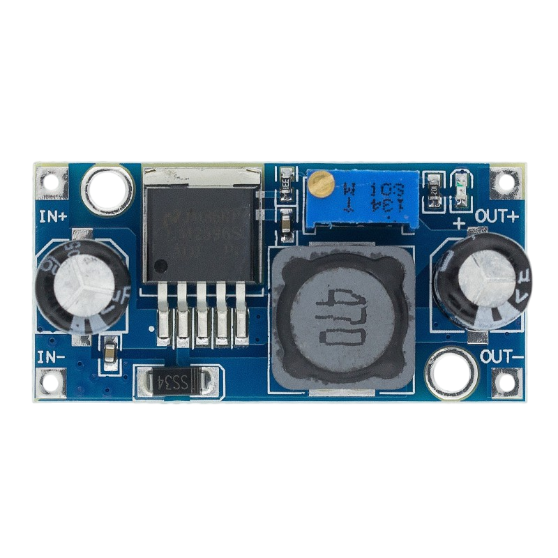
The LM2596 5V/3A is a DC-DC buck converter designed to step down a higher input voltage to a stable 5V output. It is highly efficient, compact, and capable of delivering up to 3A of current, making it ideal for powering devices that require a reliable 5V supply. This module is widely used in battery-powered systems, embedded projects, and applications where regulated 5V power is essential.

Explore Projects Built with Step Down LM2596 5V/3A

Use Cirkit Designer to design, explore, and prototype these projects online. Some projects support real-time simulation. Click "Open Project" to start designing instantly!
Voltage Regulation System with MT3608 Boost and LM2596 Buck Converters
Image of solar system router ups: A project utilizing Step Down LM2596 5V/3A in a practical application
This circuit consists of two MT3608 boost converters and an LM2596 step-down module, each connected to separate 12V power supplies. The MT3608 modules are configured to step up the voltage from their respective power supplies, while the LM2596 module steps down the voltage from a 12V battery. Diodes are used to ensure correct current flow direction, potentially for protection or isolation between different parts of the circuit.
Cirkit Designer LogoOpen Project in Cirkit Designer
12V to 5V Power Supply with LED Indicator and Push Switch
Image of Power Supply LVCO: A project utilizing Step Down LM2596 5V/3A in a practical application
This circuit is a 12V to 5V regulated power supply with an LED indicator. It uses a 5408 diode for reverse polarity protection, an LM340T5 7805 voltage regulator to step down the voltage to 5V, and a push switch to control the LED indicator. The circuit also includes capacitors for filtering and a resistor to limit the current through the LED.
Cirkit Designer LogoOpen Project in Cirkit Designer
Battery-Powered UPS with Step-Down Buck Converter and BMS
Image of Mini ups: A project utilizing Step Down LM2596 5V/3A in a practical application
This circuit is a power management system that steps down a 240V AC input to a lower DC voltage using a buck converter, which then powers a 40W UPS. The UPS is controlled by a rocker switch and is backed up by a battery management system (BMS) connected to three 3.7V batteries in series, ensuring continuous power supply.
Cirkit Designer LogoOpen Project in Cirkit Designer
USB Power Supply with Overcurrent Protection
Image of USB Charging port: A project utilizing Step Down LM2596 5V/3A in a practical application
This circuit is designed to step down voltage from a 12V battery to a lower voltage suitable for USB devices. It includes a buck converter connected to the battery through a fuse and fuse holder for overcurrent protection. The output of the buck converter is connected to a USB female port, providing a regulated power supply for USB-powered devices.
Cirkit Designer LogoOpen Project in Cirkit Designer

Explore Projects Built with Step Down LM2596 5V/3A

Use Cirkit Designer to design, explore, and prototype these projects online. Some projects support real-time simulation. Click "Open Project" to start designing instantly!
Image of solar system router ups: A project utilizing Step Down LM2596 5V/3A in a practical application
Voltage Regulation System with MT3608 Boost and LM2596 Buck Converters
This circuit consists of two MT3608 boost converters and an LM2596 step-down module, each connected to separate 12V power supplies. The MT3608 modules are configured to step up the voltage from their respective power supplies, while the LM2596 module steps down the voltage from a 12V battery. Diodes are used to ensure correct current flow direction, potentially for protection or isolation between different parts of the circuit.
Cirkit Designer LogoOpen Project in Cirkit Designer
Image of Power Supply LVCO: A project utilizing Step Down LM2596 5V/3A in a practical application
12V to 5V Power Supply with LED Indicator and Push Switch
This circuit is a 12V to 5V regulated power supply with an LED indicator. It uses a 5408 diode for reverse polarity protection, an LM340T5 7805 voltage regulator to step down the voltage to 5V, and a push switch to control the LED indicator. The circuit also includes capacitors for filtering and a resistor to limit the current through the LED.
Cirkit Designer LogoOpen Project in Cirkit Designer
Image of Mini ups: A project utilizing Step Down LM2596 5V/3A in a practical application
Battery-Powered UPS with Step-Down Buck Converter and BMS
This circuit is a power management system that steps down a 240V AC input to a lower DC voltage using a buck converter, which then powers a 40W UPS. The UPS is controlled by a rocker switch and is backed up by a battery management system (BMS) connected to three 3.7V batteries in series, ensuring continuous power supply.
Cirkit Designer LogoOpen Project in Cirkit Designer
Image of USB Charging port: A project utilizing Step Down LM2596 5V/3A in a practical application
USB Power Supply with Overcurrent Protection
This circuit is designed to step down voltage from a 12V battery to a lower voltage suitable for USB devices. It includes a buck converter connected to the battery through a fuse and fuse holder for overcurrent protection. The output of the buck converter is connected to a USB female port, providing a regulated power supply for USB-powered devices.
Cirkit Designer LogoOpen Project in Cirkit Designer

Common Applications

  • Powering microcontrollers (e.g., Arduino, Raspberry Pi)
  • Battery-powered devices
  • Robotics and IoT projects
  • LED strips and displays
  • USB-powered devices

Technical Specifications

The LM2596 5V/3A module has the following key specifications:

Parameter Value
Input Voltage Range 7V to 40V
Output Voltage 5V (fixed)
Maximum Output Current 3A
Efficiency Up to 92%
Switching Frequency 150 kHz
Operating Temperature -40°C to +85°C
Dimensions Approx. 45mm x 20mm x 14mm

Pin Configuration and Descriptions

The LM2596 module typically has three pins or terminals for connection:

Pin Name Description
VIN Input voltage (7V to 40V). Connect to the power source.
GND Ground. Common ground for input and output.
VOUT Regulated 5V output. Connect to the load.

Usage Instructions

How to Use the LM2596 5V/3A in a Circuit

  1. Connect the Input Voltage (VIN):

    • Attach the positive terminal of your power source (7V to 40V) to the VIN pin.
    • Connect the negative terminal of the power source to the GND pin.
  2. Connect the Output Load (VOUT):

    • Connect the positive terminal of your load (e.g., microcontroller, LED strip) to the VOUT pin.
    • Connect the negative terminal of your load to the GND pin.
  3. Verify Connections:

    • Double-check all connections to ensure proper polarity and avoid short circuits.
  4. Power On:

    • Turn on the power source. The module will regulate the input voltage and provide a stable 5V output.

Important Considerations and Best Practices

  • Input Voltage Range: Ensure the input voltage is within the specified range (7V to 40V). Exceeding this range may damage the module.
  • Heat Dissipation: At higher currents (close to 3A), the module may heat up. Use a heatsink or ensure proper ventilation to prevent overheating.
  • Load Current: Do not exceed the maximum output current of 3A to avoid damaging the module.
  • Polarity Protection: The module does not have built-in reverse polarity protection. Ensure correct polarity when connecting the power source.

Example: Using LM2596 with Arduino UNO

The LM2596 can be used to power an Arduino UNO by stepping down a 12V input to 5V. Below is an example circuit and Arduino code:

Circuit Connections

  • Connect a 12V DC power source to the VIN and GND pins of the LM2596.
  • Connect the VOUT pin of the LM2596 to the 5V pin of the Arduino UNO.
  • Connect the GND pin of the LM2596 to the GND pin of the Arduino UNO.

Arduino Code Example

// Example code to blink an LED connected to pin 13 of Arduino UNO
// Ensure the Arduino is powered via the LM2596 module

void setup() {
  pinMode(13, OUTPUT); // Set pin 13 as an output
}

void loop() {
  digitalWrite(13, HIGH); // Turn the LED on
  delay(1000);            // Wait for 1 second
  digitalWrite(13, LOW);  // Turn the LED off
  delay(1000);            // Wait for 1 second
}

Troubleshooting and FAQs

Common Issues and Solutions

  1. No Output Voltage:

    • Cause: Incorrect input voltage or loose connections.
    • Solution: Verify that the input voltage is within the 7V to 40V range and check all connections.
  2. Overheating:

    • Cause: High current draw or insufficient ventilation.
    • Solution: Reduce the load current or add a heatsink to the module.
  3. Output Voltage Fluctuations:

    • Cause: Input voltage instability or excessive load.
    • Solution: Use a stable power source and ensure the load does not exceed 3A.
  4. Module Not Working After Connection:

    • Cause: Reverse polarity or input voltage exceeding the maximum limit.
    • Solution: Check polarity and ensure the input voltage is within the specified range.

FAQs

Q1: Can I adjust the output voltage of the LM2596 module?
A1: No, this version of the LM2596 module has a fixed 5V output. For adjustable output, use an LM2596 adjustable module.

Q2: Can I use the LM2596 to power a Raspberry Pi?
A2: Yes, the LM2596 can power a Raspberry Pi, but ensure the input voltage is sufficient and the current draw does not exceed 3A.

Q3: Is the LM2596 suitable for battery-powered applications?
A3: Yes, the LM2596 is highly efficient and suitable for stepping down battery voltage to 5V.

Q4: Does the module have short-circuit protection?
A4: No, the LM2596 module does not have built-in short-circuit protection. Use external protection if needed.