How to Use L6203 Full Bridge Driver: Examples, Pinouts, and Specs
Introduction
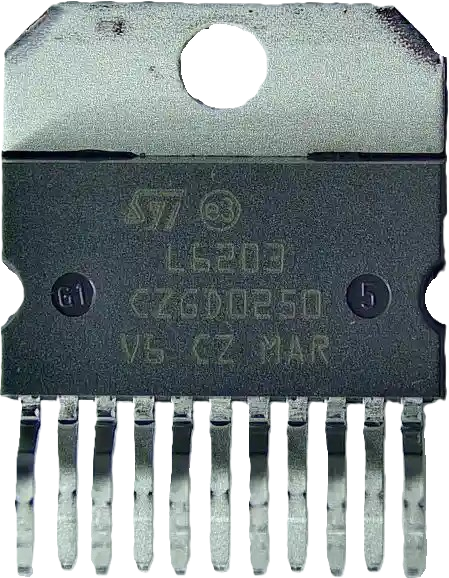
The L6203 is a dual full-bridge driver manufactured by STMicroelectronics. It is specifically designed for driving inductive loads such as DC motors and stepper motors. The L6203 allows for precise control of motor direction and speed, making it ideal for applications requiring high current output and robust protection features. With built-in thermal shutdown, overcurrent protection, and high voltage operation, the L6203 is a reliable choice for motor control in industrial, automotive, and robotic systems.
Explore Projects Built with L6203 Full Bridge Driver


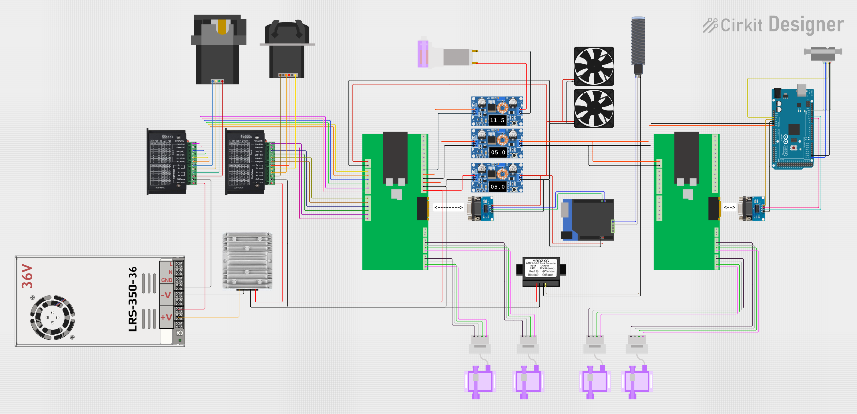

Explore Projects Built with L6203 Full Bridge Driver
Common Applications
- DC motor control for robotics and automation
- Stepper motor driving in CNC machines and 3D printers
- Industrial motorized actuators
- Automotive systems such as electric window lifters and wipers
- Home appliances requiring motorized components
Technical Specifications
Key Technical Details
| Parameter | Value |
|---|---|
| Supply Voltage (Vcc) | 12V to 48V |
| Output Current (per bridge) | Up to 4A |
| Maximum Power Dissipation | 25W (with proper heatsinking) |
| Logic Input Voltage Range | 0V to 7V |
| Operating Temperature Range | -40°C to +150°C |
| Protection Features | Thermal shutdown, overcurrent, and undervoltage protection |
Pin Configuration and Descriptions
The L6203 is available in a Multiwatt-11 package. Below is the pinout and description:
| Pin Number | Pin Name | Description |
|---|---|---|
| 1 | OUT1 | Output 1 of the first half-bridge |
| 2 | VS (Power) | Supply voltage for the power stage |
| 3 | OUT2 | Output 2 of the first half-bridge |
| 4 | GND | Ground connection |
| 5 | IN1 | Logic input 1 for controlling the first half-bridge |
| 6 | IN2 | Logic input 2 for controlling the first half-bridge |
| 7 | EN (Enable) | Enable pin for activating the driver (active high) |
| 8 | OUT3 | Output 1 of the second half-bridge |
| 9 | VS (Power) | Supply voltage for the power stage |
| 10 | OUT4 | Output 2 of the second half-bridge |
| 11 | Vref | Reference voltage for current sensing or limiting |
Usage Instructions
How to Use the L6203 in a Circuit
- Power Supply: Connect a DC power supply (12V to 48V) to the
VSpin. Ensure the supply voltage matches the motor's requirements. - Logic Inputs: Use the
IN1andIN2pins to control the direction of the motor. These pins accept standard logic levels (0V for LOW, 5V for HIGH). - Enable Pin: Set the
ENpin HIGH to activate the driver. When LOW, the driver is disabled, and the outputs are in a high-impedance state. - Motor Connections: Connect the motor terminals to the
OUT1,OUT2,OUT3, andOUT4pins, depending on the motor type (DC or stepper motor). - Heatsinking: Attach a heatsink to the L6203 to dissipate heat effectively, especially when driving high currents.
- Protection Features: The L6203 includes built-in protection for thermal shutdown and overcurrent. Ensure proper circuit design to avoid triggering these protections unnecessarily.
Example: Controlling a DC Motor with Arduino UNO
Below is an example of how to control a DC motor using the L6203 and an Arduino UNO:
// Define pin connections
const int IN1 = 7;  // Connect to L6203 IN1 pin
const int IN2 = 8;  // Connect to L6203 IN2 pin
const int EN = 9;   // Connect to L6203 EN pin

void setup() {
  // Set pin modes
  pinMode(IN1, OUTPUT);
  pinMode(IN2, OUTPUT);
  pinMode(EN, OUTPUT);

  // Enable the L6203 driver
  digitalWrite(EN, HIGH);
}

void loop() {
  // Rotate motor in one direction
  digitalWrite(IN1, HIGH);  // Set IN1 HIGH
  digitalWrite(IN2, LOW);   // Set IN2 LOW
  delay(2000);              // Run motor for 2 seconds

  // Stop the motor
  digitalWrite(IN1, LOW);
  digitalWrite(IN2, LOW);
  delay(1000);              // Pause for 1 second

  // Rotate motor in the opposite direction
  digitalWrite(IN1, LOW);   // Set IN1 LOW
  digitalWrite(IN2, HIGH);  // Set IN2 HIGH
  delay(2000);              // Run motor for 2 seconds

  // Stop the motor
  digitalWrite(IN1, LOW);
  digitalWrite(IN2, LOW);
  delay(1000);              // Pause for 1 second
}
Important Considerations
- Decoupling Capacitors: Place a decoupling capacitor (e.g., 100µF electrolytic) near the
VSpin to stabilize the power supply. - Heatsinking: Ensure adequate heatsinking to prevent thermal shutdown during high-current operation.
- Current Sensing: Use the
Vrefpin for current sensing or limiting if required by your application. - Logic Levels: Ensure the logic input levels are compatible with the L6203 (0V to 7V range).
Troubleshooting and FAQs
Common Issues and Solutions
Motor Not Spinning
- Cause: The
ENpin is not set HIGH. - Solution: Verify that the
ENpin is connected to a HIGH logic level.
- Cause: The
Driver Overheating
- Cause: Insufficient heatsinking or excessive current draw.
- Solution: Attach a proper heatsink and ensure the motor's current requirements are within the L6203's limits.
Motor Vibrates but Does Not Rotate
- Cause: Incorrect logic input signals.
- Solution: Verify the
IN1andIN2signals. Ensure they are not both HIGH or both LOW simultaneously.
Thermal Shutdown Triggered
- Cause: Prolonged high current or inadequate cooling.
- Solution: Reduce the motor load or improve the heatsink design.
No Output Voltage
- Cause: Faulty connections or undervoltage on the
VSpin. - Solution: Check all connections and ensure the supply voltage is within the specified range.
- Cause: Faulty connections or undervoltage on the
FAQs
Can the L6203 drive stepper motors? Yes, the L6203 can drive stepper motors by controlling the two full bridges independently.
What is the maximum current the L6203 can handle? The L6203 can handle up to 4A per bridge, provided proper heatsinking is used.
Is the L6203 compatible with 3.3V logic? Yes, the L6203 accepts logic levels as low as 0V and as high as 7V, making it compatible with both 3.3V and 5V systems.
Does the L6203 require external diodes for protection? No, the L6203 has built-in diodes for flyback protection, simplifying circuit design.
This concludes the documentation for the L6203 Full Bridge Driver. For further details, refer to the official datasheet provided by STMicroelectronics.