
How to Use Crystal 16MHz: Examples, Pinouts, and Specs
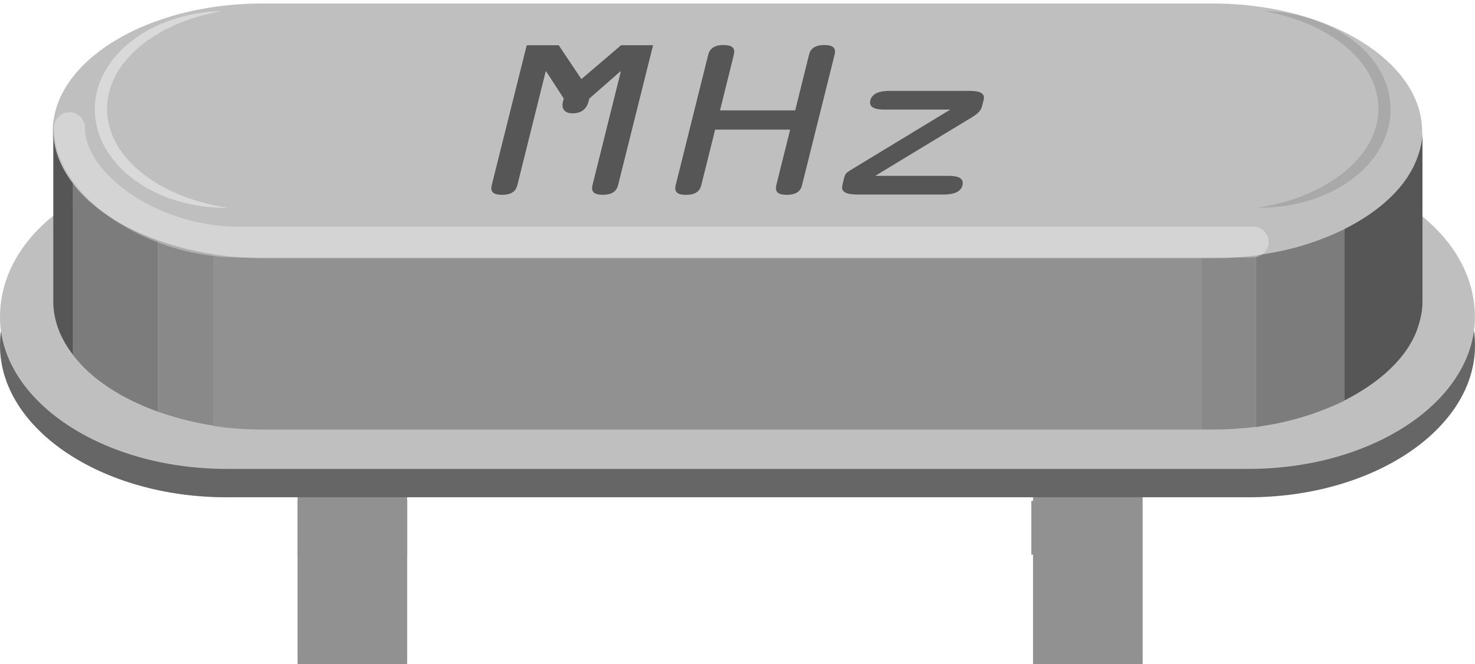
 Design with Crystal 16MHz in Cirkit Designer
Introduction
The 16MHz Crystal Oscillator is a fundamental component in many electronic circuits, providing a stable clock signal for timing purposes. This crystal oscillator is widely used in microcontroller-based projects, including those involving the Arduino UNO, to ensure precise timing and synchronization.
Explore Projects Built with Crystal 16MHz
 Open Project in Cirkit Designer
 Open Project in Cirkit Designer
 Open Project in Cirkit Designer
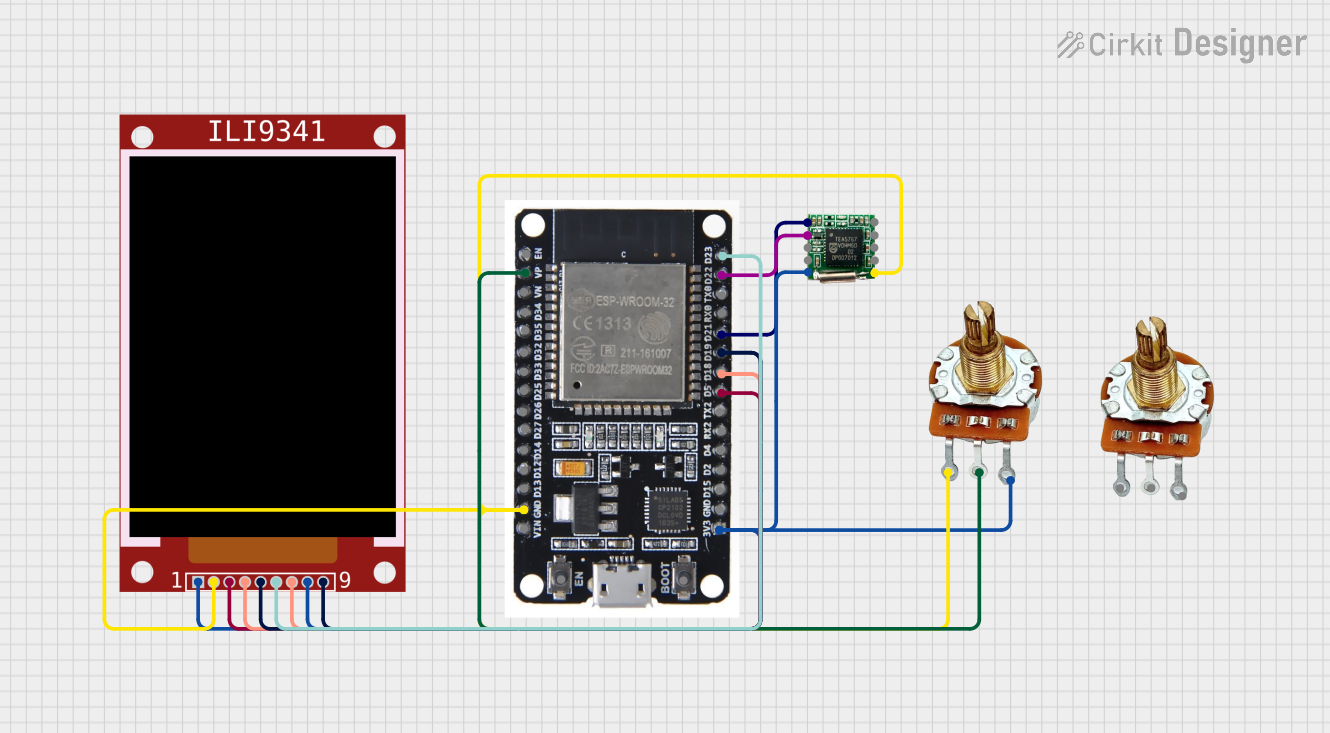
 Open Project in Cirkit Designer
Explore Projects Built with Crystal 16MHz

 Open Project in Cirkit Designer
 Open Project in Cirkit Designer
 Open Project in Cirkit Designer
 Open Project in Cirkit Designer
Common Applications and Use Cases
- Microcontroller Clock Source: Provides the clock signal for microcontrollers, ensuring accurate timing for operations.
- Communication Systems: Used in RF circuits and communication modules for stable frequency generation.
- Digital Circuits: Ensures synchronization in digital circuits, such as counters and timers.
- Embedded Systems: Integral in embedded systems for maintaining system stability and performance.
Technical Specifications
Key Technical Details
| Parameter | Value |
|---|---|
| Frequency | 16 MHz |
| Load Capacitance | 18 pF |
| Frequency Tolerance | ±30 ppm |
| Operating Temperature Range | -20°C to +70°C |
| Equivalent Series Resistance (ESR) | 50 Ω max |
| Drive Level | 100 µW max |
| Package Type | HC-49/S |
Pin Configuration and Descriptions
| Pin Number | Pin Name | Description |
|---|---|---|
| 1 | XTAL1 | Connects to the oscillator input of the microcontroller |
| 2 | XTAL2 | Connects to the oscillator output of the microcontroller |
Usage Instructions
How to Use the Component in a Circuit
Connecting to a Microcontroller:
- Connect Pin 1 (XTAL1) to the oscillator input pin of the microcontroller.
- Connect Pin 2 (XTAL2) to the oscillator output pin of the microcontroller.
- Place two capacitors (typically 18pF each) between each pin and ground to stabilize the oscillation.
Example Circuit:
Microcontroller Pin (XTAL1) ----|---- Crystal 16MHz ----|---- Microcontroller Pin (XTAL2)
                                |                       |
                                |                       |
                              18pF                    18pF
                                |                       |
                               GND                     GND
Important Considerations and Best Practices
- Capacitor Selection: Use capacitors with the correct load capacitance (typically 18pF) to ensure stable oscillation.
- PCB Layout: Place the crystal oscillator and capacitors as close to the microcontroller pins as possible to minimize noise and signal degradation.
- Avoid Excessive Drive Levels: Ensure the drive level does not exceed the specified maximum (100 µW) to prevent damage to the crystal.
Troubleshooting and FAQs
Common Issues Users Might Face
No Oscillation:
- Solution: Check the connections and ensure the capacitors are correctly placed. Verify that the crystal is not damaged.
Inaccurate Frequency:
- Solution: Ensure the load capacitors match the specified load capacitance of the crystal. Check for any external interference or noise.
Microcontroller Not Starting:
- Solution: Verify the crystal and capacitors are correctly connected. Ensure the microcontroller's fuse settings (if applicable) are configured to use the external crystal.
FAQs
Q1: Can I use a different value for the load capacitors?
- A1: It is recommended to use the specified load capacitance (18pF) for optimal performance. Using different values may result in unstable oscillation or inaccurate frequency.
Q2: How do I know if the crystal is working?
- A2: You can use an oscilloscope to check for a stable 16MHz signal at the microcontroller's oscillator pins.
Q3: Can I use the 16MHz crystal with any microcontroller?
- A3: Most microcontrollers support external crystal oscillators, but always check the microcontroller's datasheet for compatibility and connection details.
Example Code for Arduino UNO
// Example code to demonstrate the use of a 16MHz crystal with Arduino UNO

void setup() {
  // Initialize serial communication at 9600 baud rate
  Serial.begin(9600);
}

void loop() {
  // Print a message every second
  Serial.println("16MHz Crystal Oscillator is working!");
  delay(1000); // Wait for 1 second
}
This documentation provides a comprehensive guide to understanding, using, and troubleshooting the 16MHz Crystal Oscillator in your electronic projects. Whether you are a beginner or an experienced user, this guide will help you make the most of this essential component.