How to Use T73 Series 16 Channel 24V Relay - DIN Rail: Examples, Pinouts, and Specs
Introduction
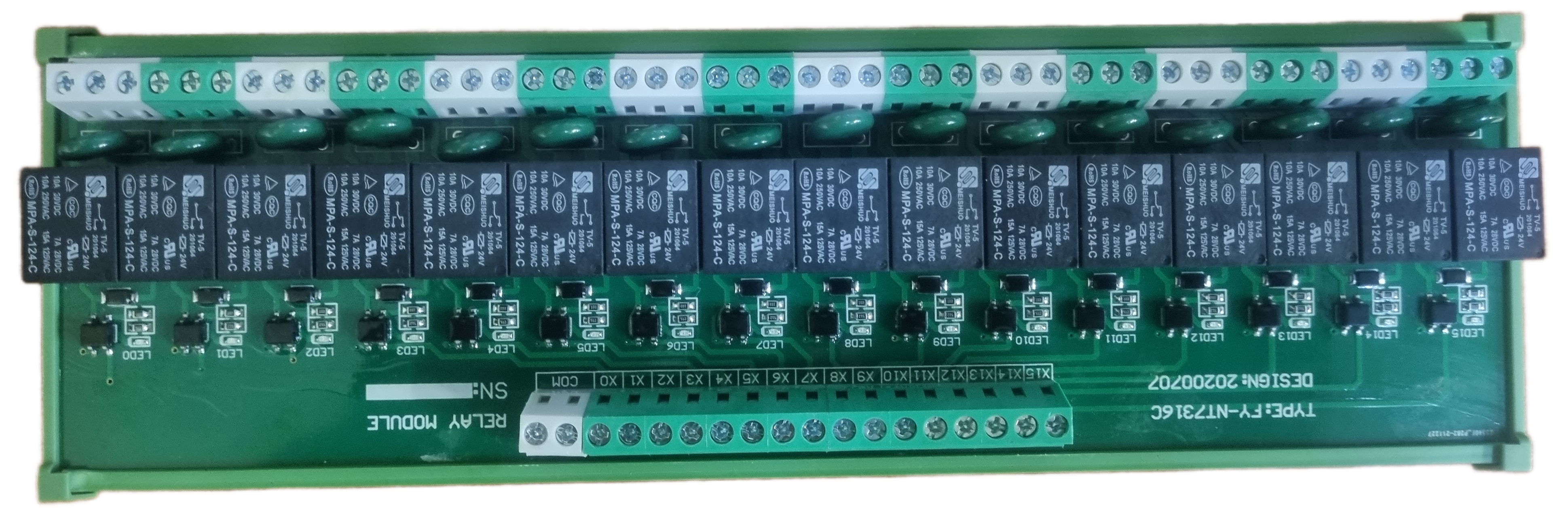
The T73 Series 16 Channel 24V Relay is an electromechanical device that operates as an electrically controlled switch. It is designed for medium to high current applications and is commonly used in industrial automation, home automation, and other applications where multiple circuits need to be controlled independently. The relay module can be easily mounted on a DIN rail, making it suitable for installation in electrical cabinets and control panels.
Explore Projects Built with T73 Series 16 Channel 24V Relay - DIN Rail

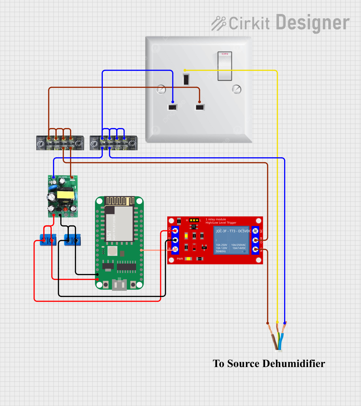
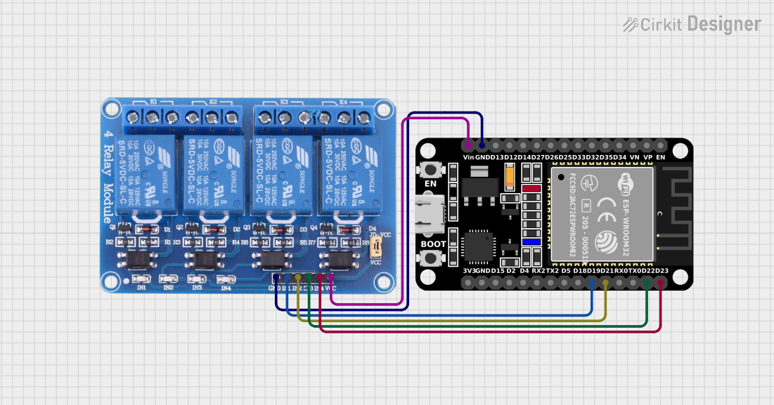

Explore Projects Built with T73 Series 16 Channel 24V Relay - DIN Rail
Common Applications and Use Cases
- Industrial automation systems
- Home automation for controlling lights, motors, and other appliances
- HVAC control systems
- Automotive electronics
- Safety-critical applications where isolation between control and load is required
Technical Specifications
Key Technical Details
- Operating Voltage: 24V DC
- Switching Current: Up to 10A per channel
- Maximum Switching Voltage: 250V AC / 30V DC
- Relay Type: Electromechanical
- Number of Channels: 16
- Isolation: Opto-isolated inputs
- Mounting Type: DIN Rail
Pin Configuration and Descriptions
| Pin Number | Description | Notes |
|---|---|---|
| 1-16 | Relay Channels (NO, NC, COM) | NO: Normally Open, NC: Normally Closed, COM: Common |
| IN1-IN16 | Input Control Signals | TTL compatible, Active Low |
| GND | Ground | Connect to system ground |
| VCC | Power Supply (24V) | Connect to 24V DC |
Usage Instructions
How to Use the Component in a Circuit
- Power Supply Connection: Connect the 24V DC power supply to the VCC and GND terminals of the relay module.
- Input Signal Connection: Connect the control signals (IN1-IN16) from your microcontroller or control device to the input terminals. Ensure that the control signals are TTL compatible and are capable of sinking the required current for relay activation.
- Load Connection: Connect the load to the relay channels. Each channel has three terminals: Normally Open (NO), Normally Closed (NC), and Common (COM). Choose NO or NC based on whether you want the load to be powered when the relay is activated or deactivated, respectively.
Important Considerations and Best Practices
- Ensure that the power supply voltage matches the relay operating voltage (24V DC).
- Do not exceed the maximum switching current and voltage ratings to avoid damaging the relay and connected devices.
- Use appropriate wire sizes for the load currents to prevent overheating and potential fire hazards.
- When controlling inductive loads (e.g., motors, solenoids), consider using snubber circuits to suppress voltage spikes.
- For safety, always disconnect power before making or changing connections.
Troubleshooting and FAQs
Common Issues Users Might Face
- Relay Not Activating: Check the input control signal and power supply connections. Ensure that the control signal is active low and the power supply is providing the correct voltage.
- Intermittent Operation: Verify that all connections are secure and that there is no loose wiring. Also, check for any signs of damage to the relay contacts due to overloading or excessive switching.
- Overheating: Ensure that the current through the relay does not exceed the rated value and that there is adequate ventilation around the relay module.
Solutions and Tips for Troubleshooting
- If the relay is not activating, measure the voltage at the input terminals to ensure that the control signal is reaching the relay.
- For intermittent operation, reseat all connections and consider using terminal blocks with screw connections for better reliability.
- If overheating occurs, reduce the load current, check for short circuits, and ensure that the relay module is not enclosed in a space with insufficient airflow.
Example Code for Arduino UNO
Below is an example code snippet for controlling one channel of the T73 Series 16 Channel 24V Relay using an Arduino UNO. This code will turn the relay on and off in a loop.
// Define the control pin for relay channel 1
const int relayPin = 2;

void setup() {
  // Set the relay control pin as an output
  pinMode(relayPin, OUTPUT);
}

void loop() {
  // Turn the relay on by setting the control pin LOW
  digitalWrite(relayPin, LOW);
  delay(1000); // Wait for 1 second

  // Turn the relay off by setting the control pin HIGH
  digitalWrite(relayPin, HIGH);
  delay(1000); // Wait for 1 second
}
Note: The control pins are active low, which means setting the pin to LOW activates the relay and setting it to HIGH deactivates it.
Remember to adjust the relayPin variable to match the input pin connected to the Arduino UNO. Repeat the setup and control logic for additional channels as needed.