
How to Use Adafruit MCP4725 Breakout Board - 12-Bit DAC: Examples, Pinouts, and Specs
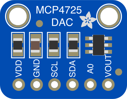
 Design with Adafruit MCP4725 Breakout Board - 12-Bit DAC in Cirkit Designer
Introduction
The Adafruit MCP4725 Breakout Board (Part ID: 935) is a high-precision digital-to-analog converter (DAC) that provides 12-bit resolution. This component allows for precise control of analog voltage output, making it ideal for applications where digital signals need to be converted into analog signals. The MCP4725 communicates via the I2C protocol, enabling easy integration with microcontrollers such as Arduino, Raspberry Pi, and others.
Explore Projects Built with Adafruit MCP4725 Breakout Board - 12-Bit DAC
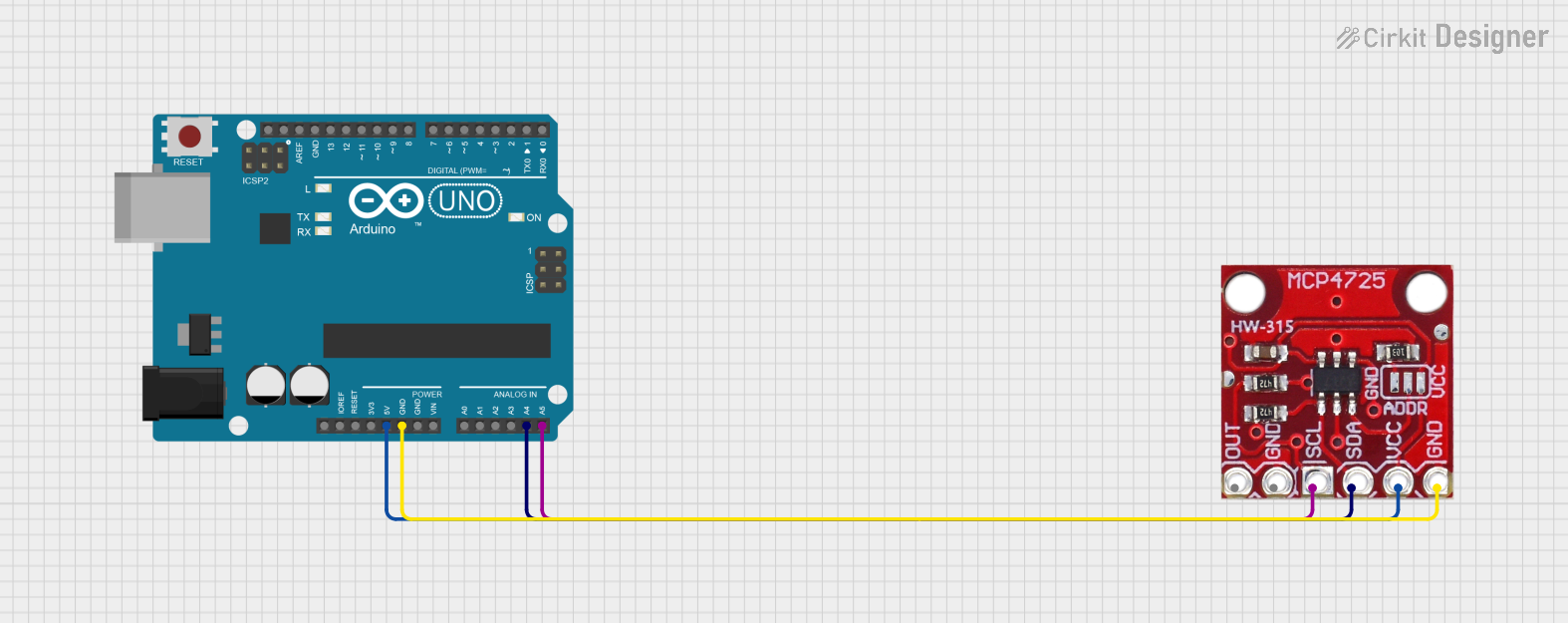 Open Project in Cirkit Designer
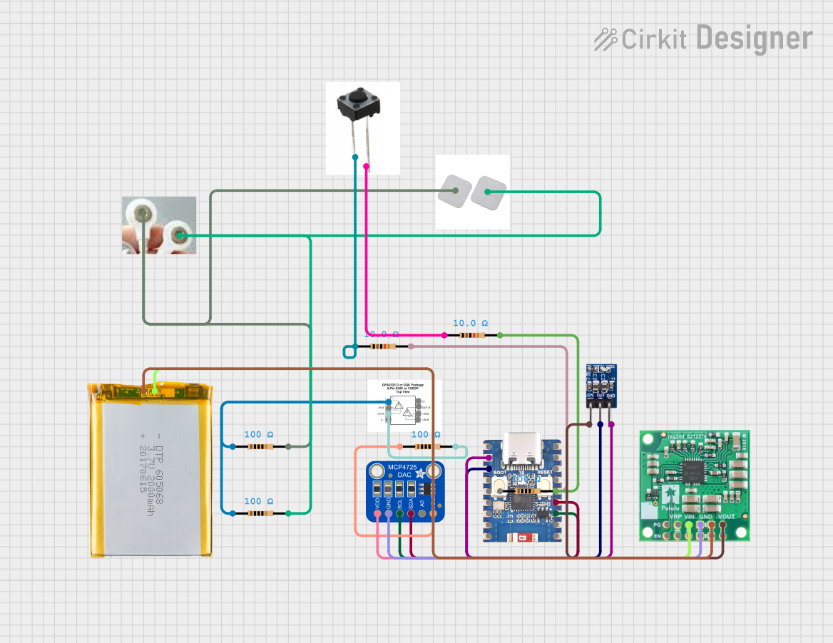 Open Project in Cirkit Designer
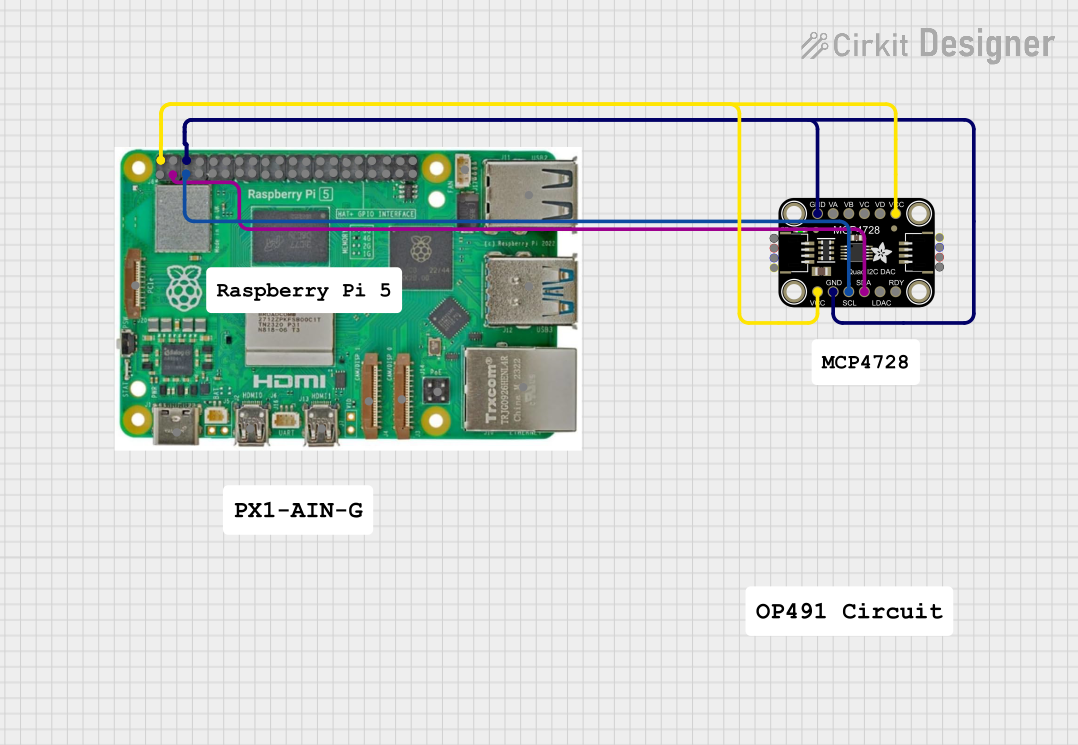 Open Project in Cirkit Designer
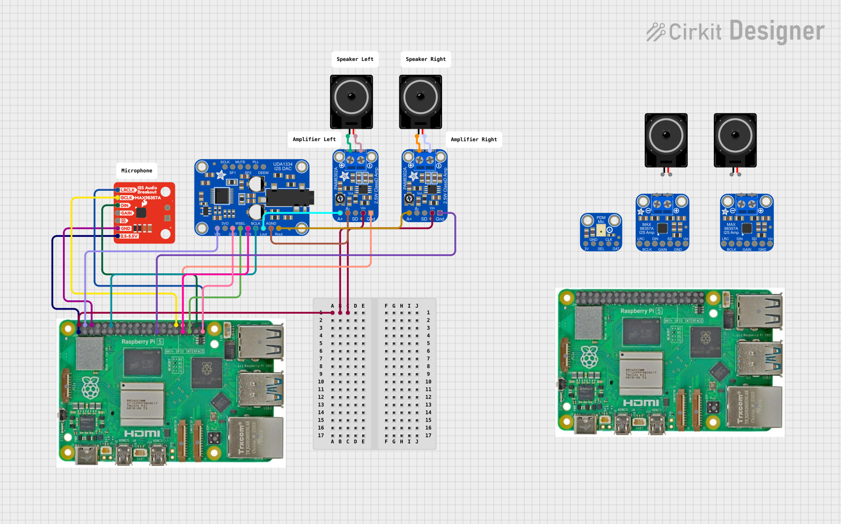 Open Project in Cirkit Designer
Explore Projects Built with Adafruit MCP4725 Breakout Board - 12-Bit DAC
Open Project in Cirkit DesignerOpen Project in Cirkit DesignerOpen Project in Cirkit DesignerOpen Project in Cirkit DesignerCommon Applications and Use Cases
- Generating analog waveforms (e.g., sine, triangle, or sawtooth waves)
- Audio signal generation
- Controlling analog devices such as motors, LEDs, or actuators
- Voltage reference generation for sensors or other circuits
- Educational projects and prototyping
Technical Specifications
The following table outlines the key technical details of the Adafruit MCP4725 Breakout Board:
| Parameter | Value |
|---|---|
| Resolution | 12-bit (4096 steps) |
| Output Voltage Range | 0V to VCC (typically 3.3V or 5V) |
| Communication Protocol | I2C |
| I2C Address (Default) | 0x60 (modifiable to 0x61) |
| Supply Voltage (VCC) | 2.7V to 5.5V |
| Maximum Output Current | 25 mA |
| Power Consumption | Low-power operation |
| Operating Temperature | -40°C to +125°C |
| Dimensions | 25mm x 17mm x 2mm |
Pin Configuration and Descriptions
The MCP4725 Breakout Board has the following pin layout:
| Pin Name | Description |
|---|---|
| VCC | Power supply input (2.7V to 5.5V). Connect to the microcontroller's power pin. |
| GND | Ground connection. Connect to the microcontroller's ground. |
| SDA | I2C data line. Connect to the microcontroller's SDA pin. |
| SCL | I2C clock line. Connect to the microcontroller's SCL pin. |
| A0 | I2C address selection pin. Leave floating or connect to GND for 0x60, or VCC for 0x61. |
Usage Instructions
How to Use the MCP4725 in a Circuit
- Power the Board: Connect the VCC pin to a 3.3V or 5V power source and the GND pin to ground.
- Connect I2C Lines: Connect the SDA and SCL pins to the corresponding I2C pins on your microcontroller.
- Set the I2C Address: Use the A0 pin to select the I2C address (default is 0x60). Leave it floating or connect to GND for 0x60, or connect to VCC for 0x61.
- Install Required Libraries: If using an Arduino, install the Adafruit MCP4725 library via the Arduino Library Manager.
- Write Code: Use the library functions to send digital values to the DAC, which will output the corresponding analog voltage.
Important Considerations and Best Practices
- Ensure the supply voltage (VCC) matches the logic level of your microcontroller (3.3V or 5V).
- Use pull-up resistors (typically 4.7kΩ) on the SDA and SCL lines if your microcontroller does not have internal pull-ups.
- Avoid exceeding the maximum output current of 25 mA to prevent damage to the DAC.
- For precise applications, minimize noise on the power supply and I2C lines.
Example Code for Arduino UNO
Below is an example of how to use the MCP4725 with an Arduino UNO to output a sine wave:
#include <Wire.h>
#include <Adafruit_MCP4725.h>

// Create an instance of the MCP4725 DAC
Adafruit_MCP4725 dac;

void setup() {
  Serial.begin(9600);
  Serial.println("Initializing MCP4725...");

  // Initialize the DAC with the default I2C address (0x60)
  if (!dac.begin(0x60)) {
    Serial.println("Failed to find MCP4725. Check connections.");
    while (1);
  }
  Serial.println("MCP4725 initialized.");
}

void loop() {
  // Generate a sine wave using the DAC
  for (int i = 0; i < 360; i++) {
    // Calculate the sine value (scaled to 12-bit range: 0-4095)
    uint16_t value = (sin(i * DEG_TO_RAD) + 1) * 2047.5;

    // Write the value to the DAC
    dac.setVoltage(value, false);

    // Delay to control the frequency of the sine wave
    delay(10);
  }
}
Code Explanation
- The
Adafruit_MCP4725library is used to interface with the DAC. - The
setVoltage()function sends a 12-bit value to the DAC, which outputs the corresponding analog voltage. - A sine wave is generated by calculating the sine of angles (in degrees) and scaling the result to the DAC's 12-bit range.
Troubleshooting and FAQs
Common Issues and Solutions
No Output Voltage:
- Verify that the VCC and GND pins are properly connected.
- Check the I2C connections (SDA and SCL) and ensure pull-up resistors are in place if needed.
- Confirm the I2C address matches the one used in your code (default is 0x60).
Incorrect or Unstable Output:
- Ensure the power supply is stable and within the specified range (2.7V to 5.5V).
- Minimize noise on the I2C lines by using short, twisted wires or a PCB.
Library Not Found:
- Install the Adafruit MCP4725 library via the Arduino Library Manager.
- Ensure the library is correctly included in your sketch (
#include <Adafruit_MCP4725.h>).
Device Not Detected:
- Use an I2C scanner sketch to confirm the MCP4725 is detected on the I2C bus.
- Check the A0 pin configuration if using a non-default I2C address.
FAQs
Q: Can I use the MCP4725 with a 3.3V microcontroller?
A: Yes, the MCP4725 is compatible with both 3.3V and 5V logic levels.
Q: What is the maximum resolution of the DAC?
A: The MCP4725 provides 12-bit resolution, meaning it can output 4096 discrete voltage levels.
Q: Can I use multiple MCP4725 boards on the same I2C bus?
A: Yes, you can use up to two MCP4725 boards by configuring their I2C addresses (0x60 and 0x61).
Q: Is the output voltage stable?
A: Yes, the MCP4725 provides stable output voltage, but ensure a clean power supply for optimal performance.
This concludes the documentation for the Adafruit MCP4725 Breakout Board - 12-Bit DAC.