
How to Use stepper motor and driver: Examples, Pinouts, and Specs
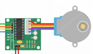
 Design with stepper motor and driver in Cirkit Designer
Introduction
A stepper motor is a type of DC motor that moves in discrete steps, allowing precise control of position, speed, and acceleration. It is commonly used in applications requiring accurate positioning, such as 3D printers, CNC machines, robotics, and camera gimbals. To operate a stepper motor, a driver circuit is required to control the current flow through the motor's coils, enabling step-by-step movement.
Stepper motor drivers simplify the process of controlling the motor by providing an interface for microcontrollers or other control systems. Popular stepper motor drivers include the A4988 and DRV8825.
Explore Projects Built with stepper motor and driver
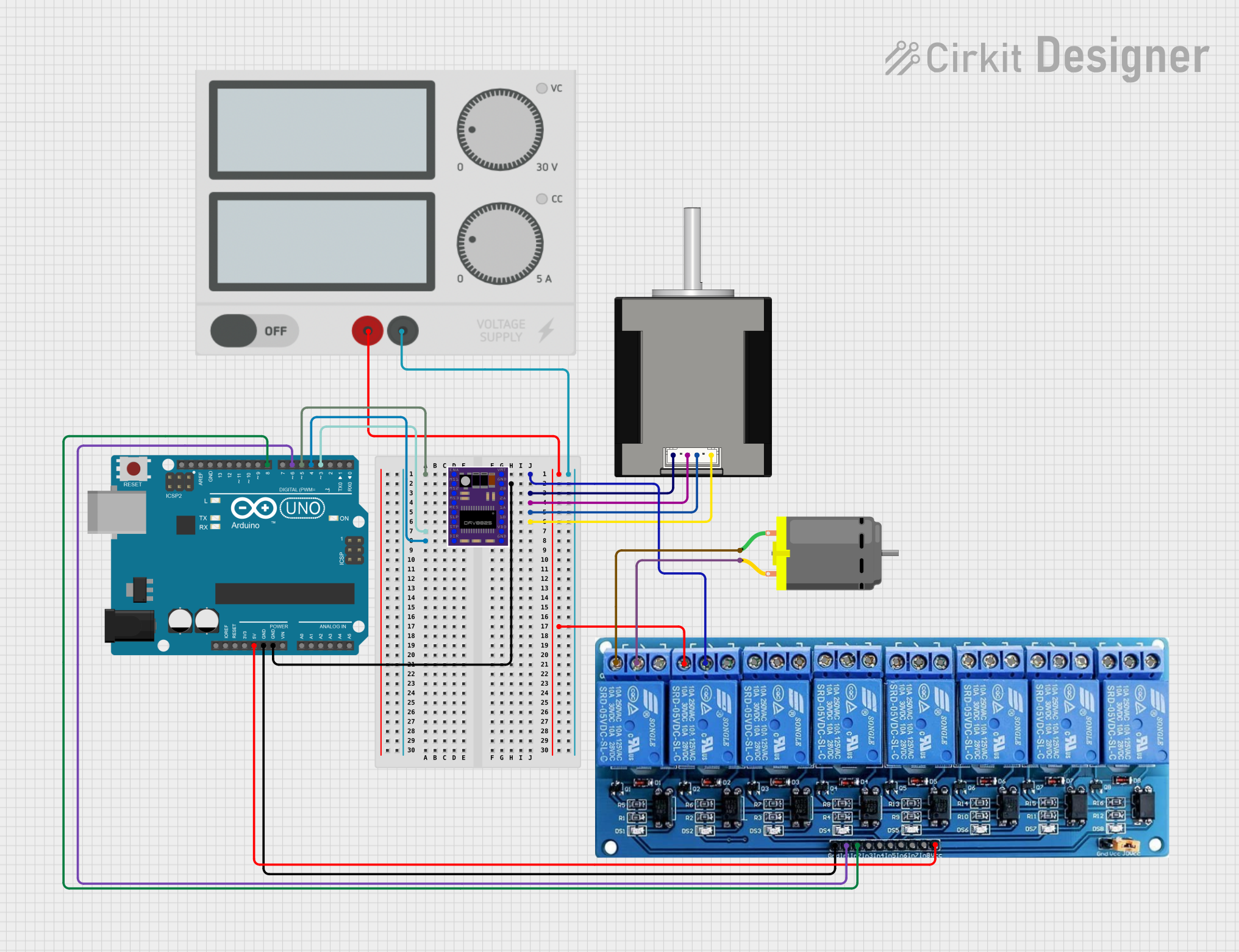 Open Project in Cirkit Designer
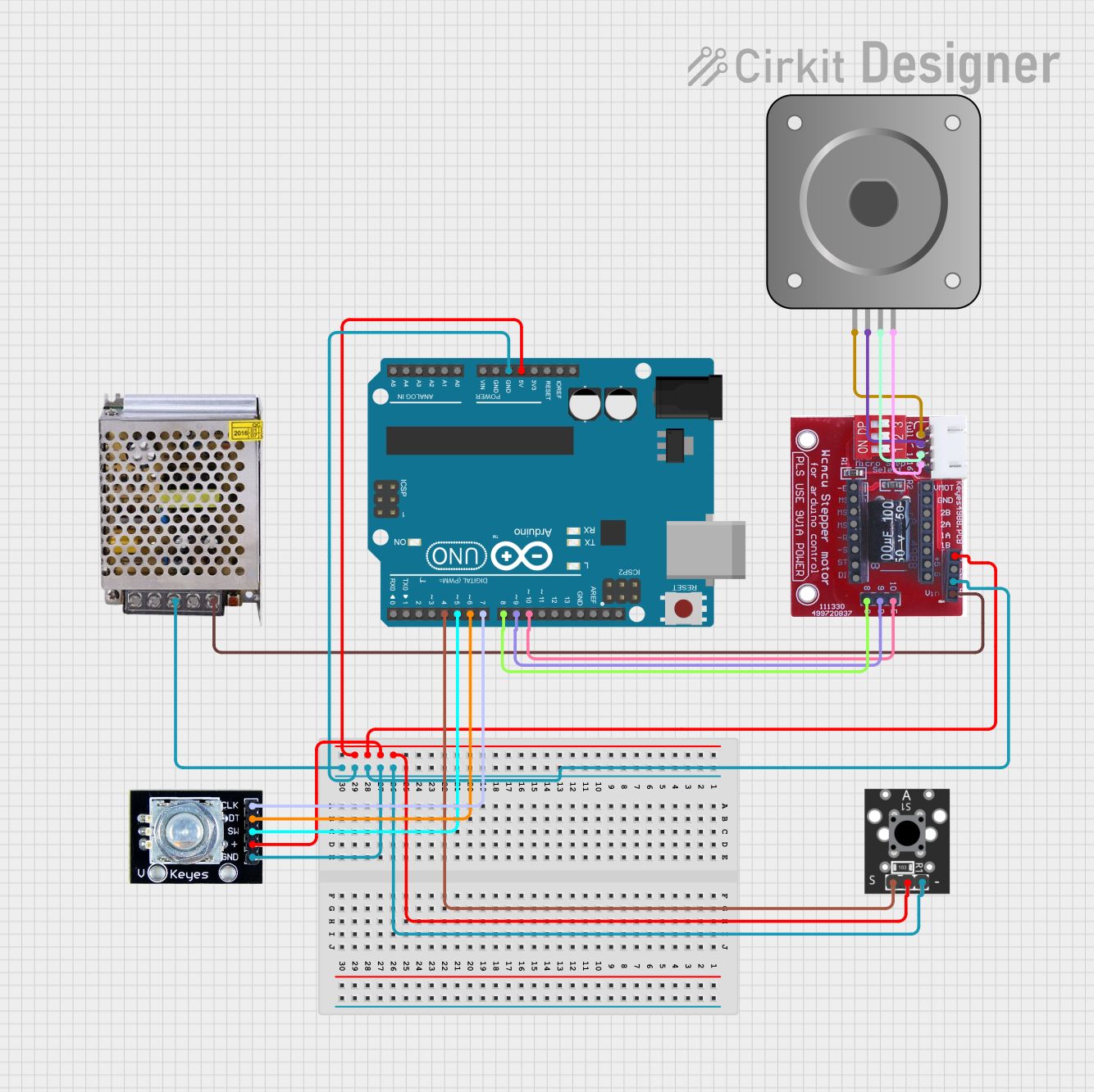 Open Project in Cirkit Designer
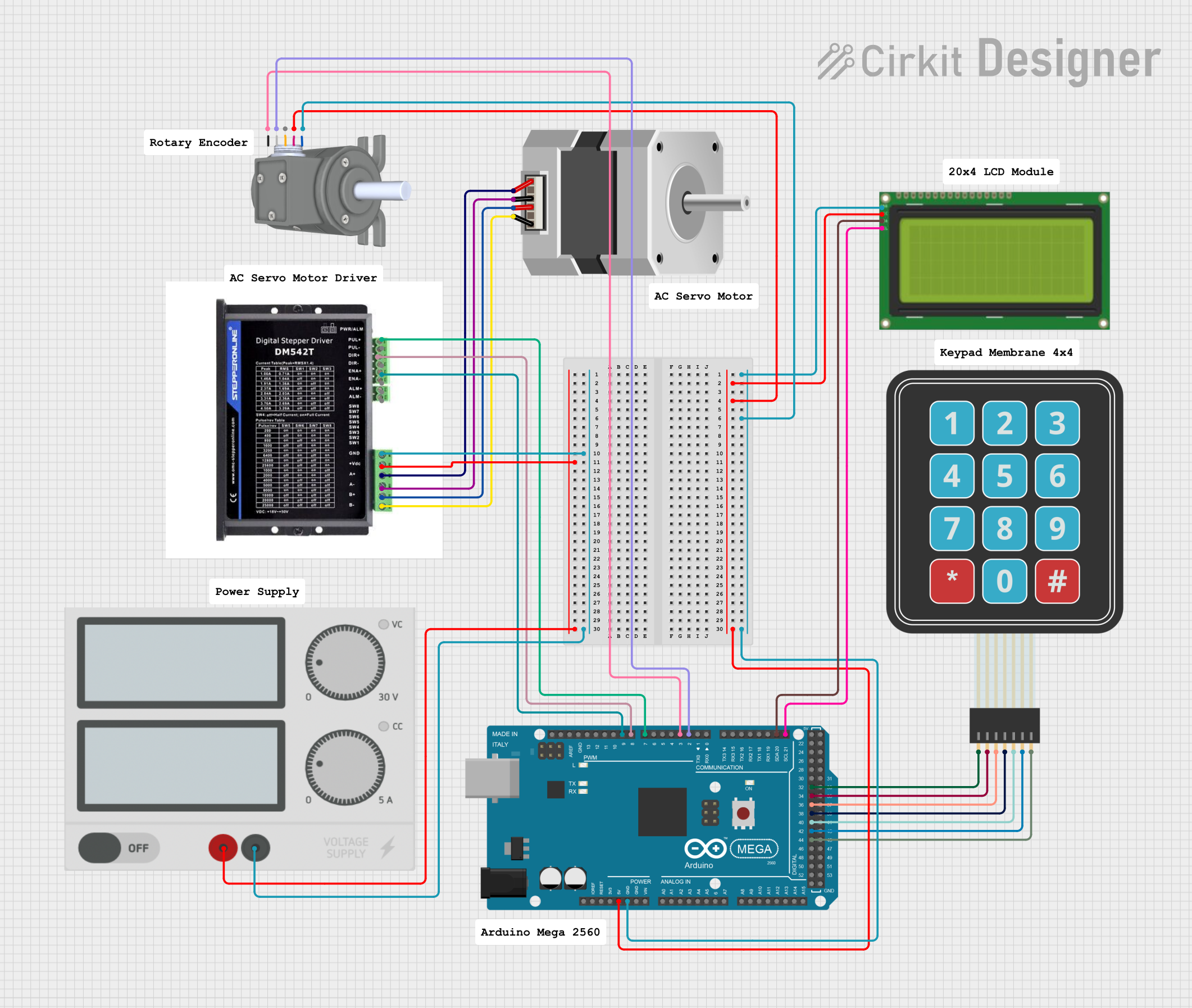 Open Project in Cirkit Designer
 Open Project in Cirkit Designer
Explore Projects Built with stepper motor and driver
Open Project in Cirkit DesignerOpen Project in Cirkit DesignerOpen Project in Cirkit DesignerOpen Project in Cirkit DesignerTechnical Specifications
Stepper Motor Specifications
| Parameter | Value |
|---|---|
| Step Angle | 1.8° (200 steps per revolution) |
| Voltage Range | 3V to 12V (varies by model) |
| Current Rating | 1A to 2A per phase (typical) |
| Holding Torque | 0.2 Nm to 1 Nm (varies by model) |
| Number of Phases | 2 (bipolar) or 4 (unipolar) |
| Shaft Diameter | 5mm (common) |
Stepper Motor Driver (e.g., A4988) Specifications
| Parameter | Value |
|---|---|
| Operating Voltage | 8V to 35V |
| Logic Voltage | 3.3V or 5V |
| Maximum Current Output | 2A per coil (with cooling) |
| Microstepping Modes | Full, 1/2, 1/4, 1/8, 1/16 steps |
| Control Interface | Step and Direction pins |
| Overcurrent Protection | Yes |
| Thermal Shutdown | Yes |
Pin Configuration for A4988 Driver
| Pin Name | Description |
|---|---|
| VMOT | Motor power supply (8V to 35V) |
| GND | Ground connection for motor power supply |
| VDD | Logic power supply (3.3V or 5V) |
| STEP | Pulse input to control motor steps |
| DIR | Direction control input (high/low) |
| ENABLE | Enable/disable motor driver (active low) |
| MS1, MS2, MS3 | Microstepping mode selection pins |
| 1A, 1B, 2A, 2B | Outputs to connect to the stepper motor coils |
Usage Instructions
Connecting the Stepper Motor and Driver
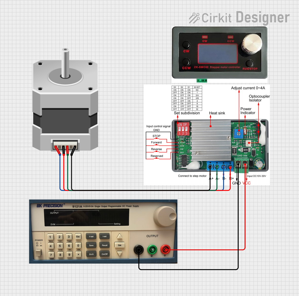
- Power Supply: Connect the motor power supply (VMOT) and ground (GND) to the driver. Ensure the voltage matches the motor's requirements.
- Logic Power: Connect the VDD pin to the 5V or 3.3V output of your microcontroller.
- Motor Connections: Connect the stepper motor's coils to the driver outputs (1A, 1B, 2A, 2B). Refer to the motor's datasheet to identify the coil pairs.
- Control Pins: Connect the STEP and DIR pins to the microcontroller's digital output pins. Optionally, connect ENABLE and microstepping pins (MS1, MS2, MS3) as needed.
Example Arduino Code
Below is an example of controlling a stepper motor using an A4988 driver and an Arduino UNO:
// Define control pins
#define STEP_PIN 3  // Pin connected to STEP on the driver
#define DIR_PIN 4   // Pin connected to DIR on the driver

void setup() {
  pinMode(STEP_PIN, OUTPUT); // Set STEP pin as output
  pinMode(DIR_PIN, OUTPUT);  // Set DIR pin as output

  digitalWrite(DIR_PIN, HIGH); // Set initial direction (HIGH = clockwise)
}

void loop() {
  // Rotate the motor one step at a time
  digitalWrite(STEP_PIN, HIGH); // Generate a step pulse
  delayMicroseconds(1000);      // Wait for 1ms (adjust for speed)
  digitalWrite(STEP_PIN, LOW);  // End the step pulse
  delayMicroseconds(1000);      // Wait for 1ms before the next step
}
Important Considerations
- Current Limiting: Adjust the current limit on the driver using the potentiometer to match the motor's rated current. This prevents overheating and damage.
- Cooling: Use a heatsink or active cooling for the driver if operating near its maximum current rating.
- Microstepping: Configure the MS1, MS2, and MS3 pins to set the desired microstepping mode for smoother motion.
- Power Sequence: Always connect the motor and driver before powering the system to avoid damaging the driver.
Troubleshooting and FAQs
Common Issues
Motor Not Moving:
- Check the power supply connections and ensure the voltage is within the required range.
- Verify the STEP and DIR signals from the microcontroller.
- Ensure the motor coils are correctly connected to the driver.
Overheating Driver:
- Reduce the current limit using the potentiometer on the driver.
- Add a heatsink or fan for better cooling.
Jerky or Inconsistent Motion:
- Check the microstepping configuration (MS1, MS2, MS3 pins).
- Ensure the STEP signal timing is consistent and not too fast for the motor.
Motor Vibrates but Doesn't Rotate:
- Verify the coil connections. Incorrect wiring can cause the motor to vibrate without rotating.
- Check the DIR pin signal to ensure the direction is set correctly.
FAQs
Can I use a unipolar stepper motor with a bipolar driver?
Yes, but only the two center-tapped coils of the unipolar motor should be connected to the driver. Leave the center taps unconnected.What is microstepping, and why is it useful?
Microstepping divides each full step into smaller steps, providing smoother motion and higher resolution.How do I calculate the delay for a specific motor speed?
The delay between STEP pulses determines the motor speed. Use the formula:Delay (µs) = (60 * 1,000,000) / (Steps per Revolution * RPM)
For example, for 200 steps/rev at 60 RPM:Delay = (60 * 1,000,000) / (200 * 60) = 5000 µs.
By following this documentation, you can effectively use a stepper motor and driver in your projects!