
How to Use Graphical LCD 128x64: Examples, Pinouts, and Specs
 Design with Graphical LCD 128x64 in Cirkit Designer
Introduction
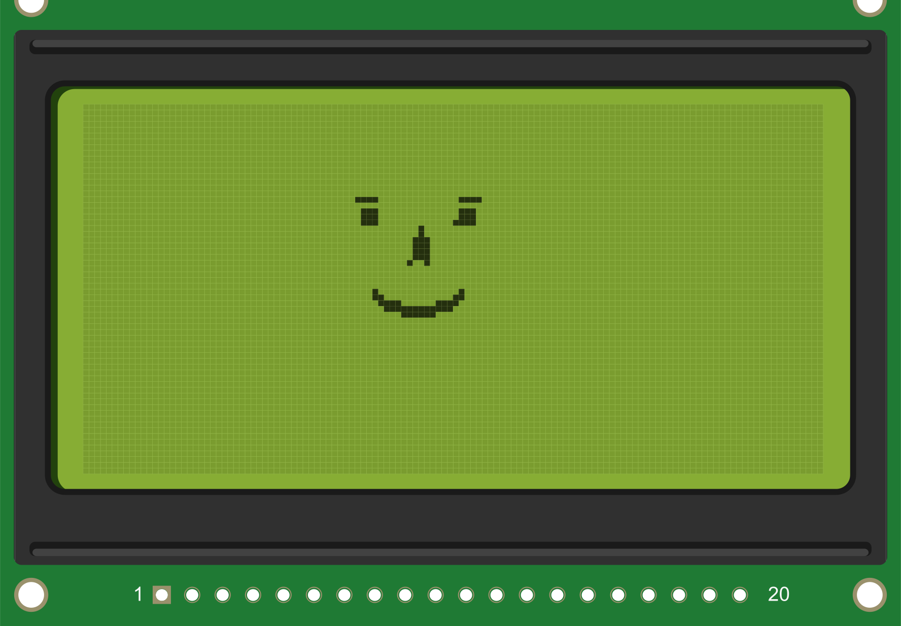
The Graphical LCD 128x64 is a liquid crystal display module with a resolution of 128x64 pixels. Unlike character-based LCDs, this graphical LCD allows for the display of complex graphics, custom fonts, and detailed text. It is widely used in embedded systems for applications requiring a visual interface, such as industrial control panels, DIY electronics projects, and portable devices.
Explore Projects Built with Graphical LCD 128x64
 Open Project in Cirkit Designer
 Open Project in Cirkit Designer
 Open Project in Cirkit Designer
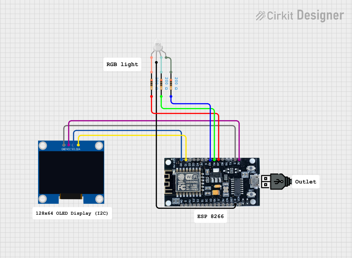 Open Project in Cirkit Designer
Explore Projects Built with Graphical LCD 128x64
Open Project in Cirkit DesignerOpen Project in Cirkit DesignerOpen Project in Cirkit DesignerOpen Project in Cirkit DesignerCommon Applications
- Displaying custom graphics, icons, and animations
- User interfaces for embedded systems
- Data visualization in scientific instruments
- Portable gaming devices
- Industrial monitoring systems
Technical Specifications
The following table outlines the key technical details of the Graphical LCD 128x64:
| Parameter | Value |
|---|---|
| Display Type | Graphical LCD |
| Resolution | 128x64 pixels |
| Operating Voltage | 4.5V to 5.5V |
| Operating Current | ~2mA (backlight off) |
| Backlight Voltage | 4.2V to 4.5V |
| Backlight Current | ~100mA |
| Communication Interface | Parallel (8-bit or 4-bit) |
| Controller IC | KS0108 or equivalent |
| Operating Temperature | -20°C to +70°C |
| Dimensions | ~93mm x 70mm x 12mm |
Pin Configuration
The Graphical LCD 128x64 typically has a 20-pin interface. Below is the pin configuration:
| Pin | Name | Description |
|---|---|---|
| 1 | VSS | Ground (0V) |
| 2 | VDD | Power supply (+5V) |
| 3 | VO | Contrast adjustment (connect to a potentiometer) |
| 4 | RS | Register Select (0: Command, 1: Data) |
| 5 | R/W | Read/Write control (0: Write, 1: Read) |
| 6 | E | Enable signal (triggers data read/write) |
| 7-14 | DB0-DB7 | Data bus lines (DB0: LSB, DB7: MSB) |
| 15 | CS1 | Chip Select 1 (activates left half of the display) |
| 16 | CS2 | Chip Select 2 (activates right half of the display) |
| 17 | RST | Reset signal (active low) |
| 18 | VOUT | Voltage output for contrast circuit (connect to a capacitor if required) |
| 19 | A | Backlight anode (+) |
| 20 | K | Backlight cathode (-) |
Usage Instructions
Connecting the Graphical LCD
- Power Supply: Connect the VSS pin to ground and the VDD pin to a +5V power source.
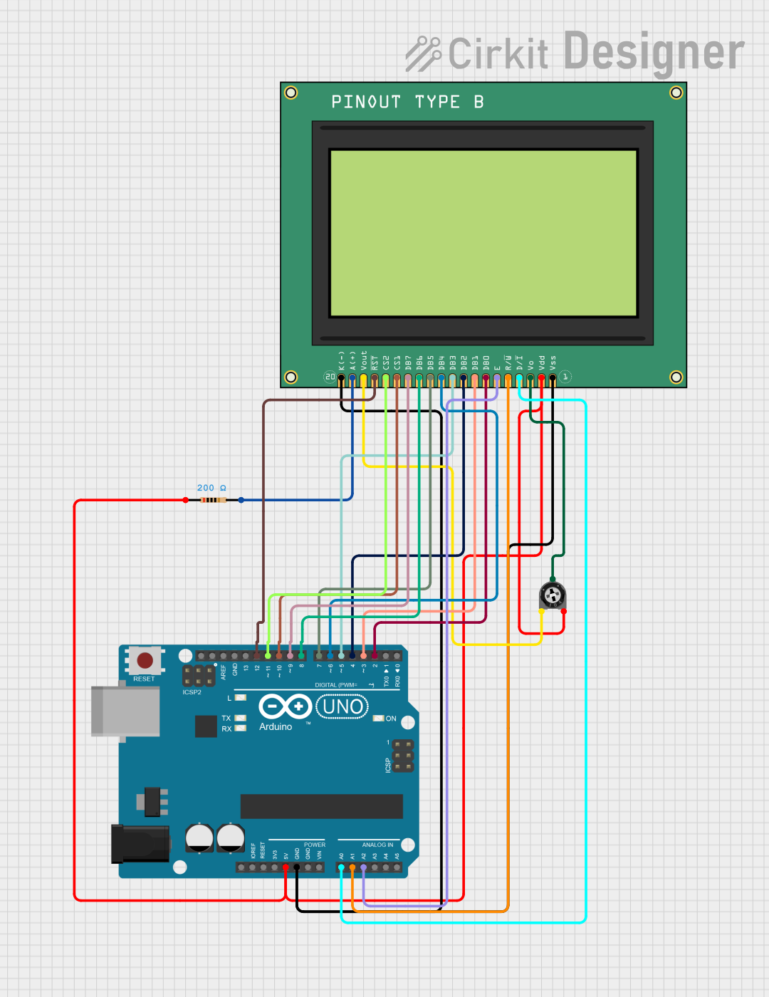
- Contrast Adjustment: Connect the VO pin to the wiper of a 10kΩ potentiometer. Connect one end of the potentiometer to ground and the other to +5V. Adjust the potentiometer to set the display contrast.
- Data Bus: Connect the DB0-DB7 pins to the microcontroller's data pins. For 4-bit mode, only DB4-DB7 are used.
- Control Pins: Connect RS, R/W, and E to the microcontroller's GPIO pins.
- Chip Select: Connect CS1 and CS2 to GPIO pins to control the left and right halves of the display.
- Backlight: Connect the A and K pins to a 4.2V power source (with a current-limiting resistor if necessary).
Example Code for Arduino UNO
Below is an example of how to interface the Graphical LCD 128x64 with an Arduino UNO using the U8glib library:
#include <U8glib.h>

// Initialize the display with the KS0108 controller
U8GLIB_KS0108_128 u8g(U8G_PIN_NONE);

void setup() {
  // Begin communication with the display
  u8g.begin();
}

void loop() {
  // Start the display drawing process
  u8g.firstPage();
  do {
    // Draw a simple message on the screen
    u8g.setFont(u8g_font_6x10); // Set font size
    u8g.drawStr(10, 20, "Hello, World!"); // Display text at (10, 20)

    // Draw a rectangle
    u8g.drawBox(50, 30, 40, 20); // Draw a filled rectangle at (50, 30)

    // Draw a circle
    u8g.drawCircle(90, 50, 10); // Draw a circle with radius 10 at (90, 50)
  } while (u8g.nextPage());

  // Add a delay to avoid rapid screen refresh
  delay(500);
}
Best Practices
- Use a decoupling capacitor (e.g., 0.1µF) between VDD and VSS to reduce noise.
- Avoid applying excessive voltage to the backlight to prevent damage.
- Ensure proper grounding to avoid display flickering or instability.
- Use a level shifter if interfacing with a 3.3V microcontroller.
Troubleshooting and FAQs
Common Issues
Display is Blank:
- Check the power supply connections (VDD and VSS).
- Adjust the contrast using the potentiometer connected to VO.
- Verify that the chip select pins (CS1 and CS2) are properly configured.
Flickering or Unstable Display:
- Ensure proper grounding and use a decoupling capacitor.
- Check the timing of the enable (E) signal.
Backlight Not Working:
- Verify the backlight connections (A and K).
- Ensure the backlight voltage does not exceed the specified range.
Incorrect or Garbled Graphics:
- Check the data bus connections (DB0-DB7).
- Ensure the RS, R/W, and E signals are correctly timed.
FAQs
Q: Can I use this display with a 3.3V microcontroller?
A: Yes, but you will need a level shifter to convert the 3.3V logic signals to 5V.
Q: How do I display custom graphics?
A: Use a graphics library like U8glib or Adafruit GFX to create and render custom bitmaps.
Q: Can I use this display in bright sunlight?
A: The display is not sunlight-readable. Consider using a transflective or OLED display for outdoor applications.
Q: What is the lifespan of the backlight?
A: The backlight typically lasts for 10,000 to 50,000 hours, depending on usage and operating conditions.