Cirkit Designer
Your all-in-one circuit design IDE
Home /
Component Documentation
How to Use Step-Down Converter: Examples, Pinouts, and Specs
Introduction
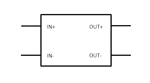
A Step-Down Converter, commonly referred to as a Buck Converter, is an essential electronic component used in power management applications. It is a type of DC-DC converter that efficiently reduces an input voltage to a lower output voltage while allowing control over the output current. This component is widely used in battery-operated devices, power supplies, and portable electronics to extend battery life and optimize power consumption.
Explore Projects Built with Step-Down Converter
Battery-Powered UPS with Step-Down Buck Converter and BMS

This circuit is a power management system that steps down a 240V AC input to a lower DC voltage using a buck converter, which then powers a 40W UPS. The UPS is controlled by a rocker switch and is backed up by a battery management system (BMS) connected to three 3.7V batteries in series, ensuring continuous power supply.
Arduino Mega 2560-Based Robotic System with Stepper Motors and IR Sensors

This circuit is a control system powered by a 12V to 5V step-down converter, featuring an Arduino Mega 2560 microcontroller that interfaces with various sensors (IR sensors, limit switch), actuators (servos, stepper motors), and a 20x4 LCD display. The system is designed to monitor inputs from sensors and control outputs to motors and display information, suitable for applications like automation or robotics.
Battery-Powered DC Generator with XL4015 Buck Converter

This circuit consists of a 12V battery connected to a rocker switch, which controls the input to an XL4015 DC Buck Step-down converter. The converter steps down the voltage to power a DC generator, with the generator's output connected back to the converter to form a feedback loop.
USB Power Supply with Overcurrent Protection

This circuit is designed to step down voltage from a 12V battery to a lower voltage suitable for USB devices. It includes a buck converter connected to the battery through a fuse and fuse holder for overcurrent protection. The output of the buck converter is connected to a USB female port, providing a regulated power supply for USB-powered devices.
Explore Projects Built with Step-Down Converter
Battery-Powered UPS with Step-Down Buck Converter and BMS
This circuit is a power management system that steps down a 240V AC input to a lower DC voltage using a buck converter, which then powers a 40W UPS. The UPS is controlled by a rocker switch and is backed up by a battery management system (BMS) connected to three 3.7V batteries in series, ensuring continuous power supply.
Arduino Mega 2560-Based Robotic System with Stepper Motors and IR Sensors
This circuit is a control system powered by a 12V to 5V step-down converter, featuring an Arduino Mega 2560 microcontroller that interfaces with various sensors (IR sensors, limit switch), actuators (servos, stepper motors), and a 20x4 LCD display. The system is designed to monitor inputs from sensors and control outputs to motors and display information, suitable for applications like automation or robotics.
Battery-Powered DC Generator with XL4015 Buck Converter
This circuit consists of a 12V battery connected to a rocker switch, which controls the input to an XL4015 DC Buck Step-down converter. The converter steps down the voltage to power a DC generator, with the generator's output connected back to the converter to form a feedback loop.
USB Power Supply with Overcurrent Protection
This circuit is designed to step down voltage from a 12V battery to a lower voltage suitable for USB devices. It includes a buck converter connected to the battery through a fuse and fuse holder for overcurrent protection. The output of the buck converter is connected to a USB female port, providing a regulated power supply for USB-powered devices.
Common Applications and Use Cases
- Voltage regulation for low-power devices
- Powering LEDs with constant current
- Battery charging circuits
- Embedded systems and microcontroller power supplies
- Automotive electronics to step down battery voltage
Technical Specifications
Key Technical Details
- Input Voltage Range: Typically ranges from a few volts above the desired output to tens of volts.
- Output Voltage Range: Usually adjustable via external components.
- Maximum Output Current: Determined by the converter design and cooling.
- Efficiency: Varies with load, but typically between 80% to 95%.
- Switching Frequency: Can range from tens of kHz to several MHz.
Pin Configuration and Descriptions
| Pin Number | Name | Description |
|---|---|---|
| 1 | VIN | Input voltage supply pin. Connect to the source voltage. |
| 2 | GND | Ground reference for the converter. |
| 3 | VOUT | Regulated output voltage pin. |
| 4 | EN | Enable pin for turning the converter on or off. |
| 5 | FB | Feedback pin for output voltage regulation. |
| 6 | SW | Switch node, connected to the internal switching element. |
Usage Instructions
How to Use the Component in a Circuit
- Input Supply: Connect a voltage source to the VIN pin, ensuring it is within the specified input range.
- Output Load: Connect your load to the VOUT pin.
- Grounding: Connect the GND pin to the system ground.
- Enable Pin: Apply a high logic level to the EN pin to turn on the converter.
- Feedback Network: Set up the feedback network using resistors to adjust the output voltage as required.
Important Considerations and Best Practices
- Heat Management: Ensure adequate cooling for the converter, especially at high output currents.
- Input Capacitor: Place a high-quality capacitor close to the VIN pin to stabilize input supply.
- Output Capacitor: Use a low ESR capacitor at the output to minimize voltage ripple.
- Switching Noise: Keep the layout compact to reduce EMI and switching noise.
- Feedback Path: Keep the feedback path short and away from noisy traces.
Troubleshooting and FAQs
Common Issues Users Might Face
- Output Voltage Too High/Low: Check the feedback network and ensure correct resistor values.
- Converter Not Starting: Verify the EN pin voltage and input voltage range.
- Excessive Heat: Check for overloading or insufficient cooling.
Solutions and Tips for Troubleshooting
- No Output: Ensure that the EN pin is correctly driven and that the input voltage is within specifications.
- Voltage Fluctuations: Strengthen input and output filtering with appropriate capacitors.
- Noise Issues: Review the PCB layout for proper grounding and minimize the loop areas.
FAQs
- Q: Can I use a step-down converter without an external inductor?
- A: No, buck converters require an external inductor for energy storage and proper operation.
- Q: What is the purpose of the feedback pin?
- A: The feedback pin is used to regulate the output voltage by comparing it with a reference voltage.
Example Code for Arduino UNO
// Example code to control a Step-Down Converter with an Arduino UNO
// This example assumes the converter has a digital enable pin

const int enablePin = 3; // Connect the EN pin of the converter to digital pin 3

void setup() {
  pinMode(enablePin, OUTPUT); // Set the enable pin as an output
  digitalWrite(enablePin, LOW); // Start with the converter disabled
}

void loop() {
  // Enable the converter
  digitalWrite(enablePin, HIGH);
  delay(5000); // Keep the converter on for 5 seconds

  // Disable the converter
  digitalWrite(enablePin, LOW);
  delay(5000); // Keep the converter off for 5 seconds
}
Note: The above code is a simple example to illustrate enabling and disabling the step-down converter using an Arduino UNO. The actual implementation may require additional considerations based on the specific converter model and application requirements.