How to Use DC Breaker 20A: Examples, Pinouts, and Specs
Introduction
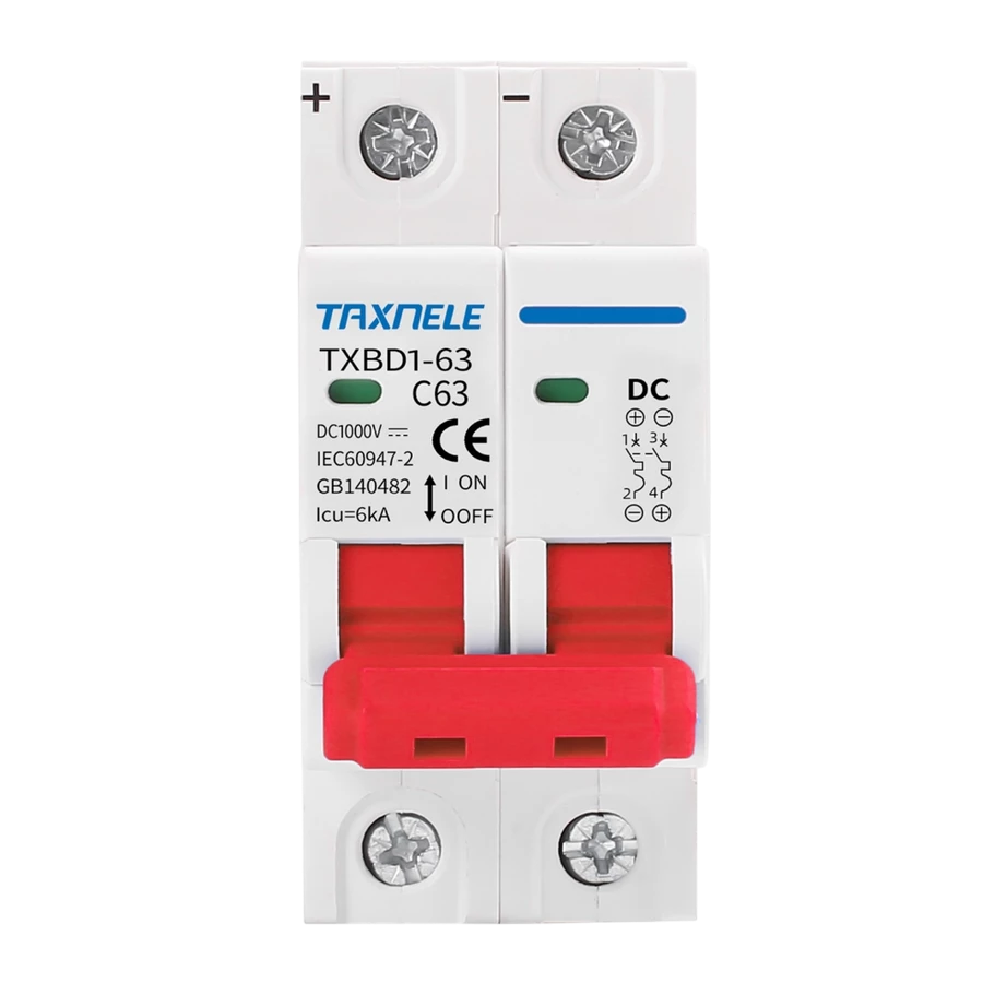
The DC Breaker 20A is a protective device designed to safeguard electrical circuits from overloads and short circuits. It is rated for a maximum current of 20 amps and is specifically engineered for use in direct current (DC) systems. By interrupting the flow of current during fault conditions, the breaker prevents damage to connected components and reduces the risk of fire or equipment failure.
Explore Projects Built with DC Breaker 20A


Explore Projects Built with DC Breaker 20A
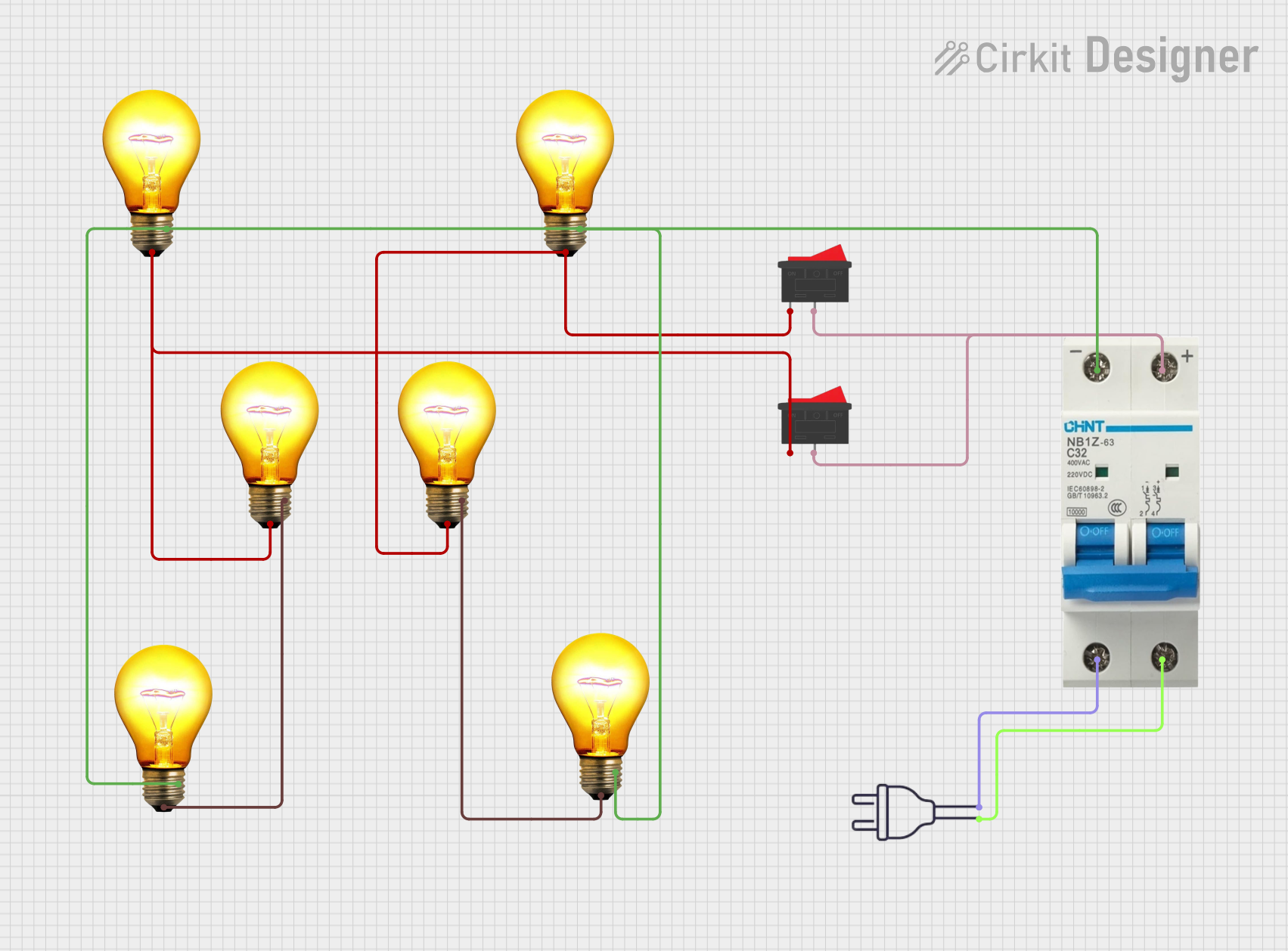
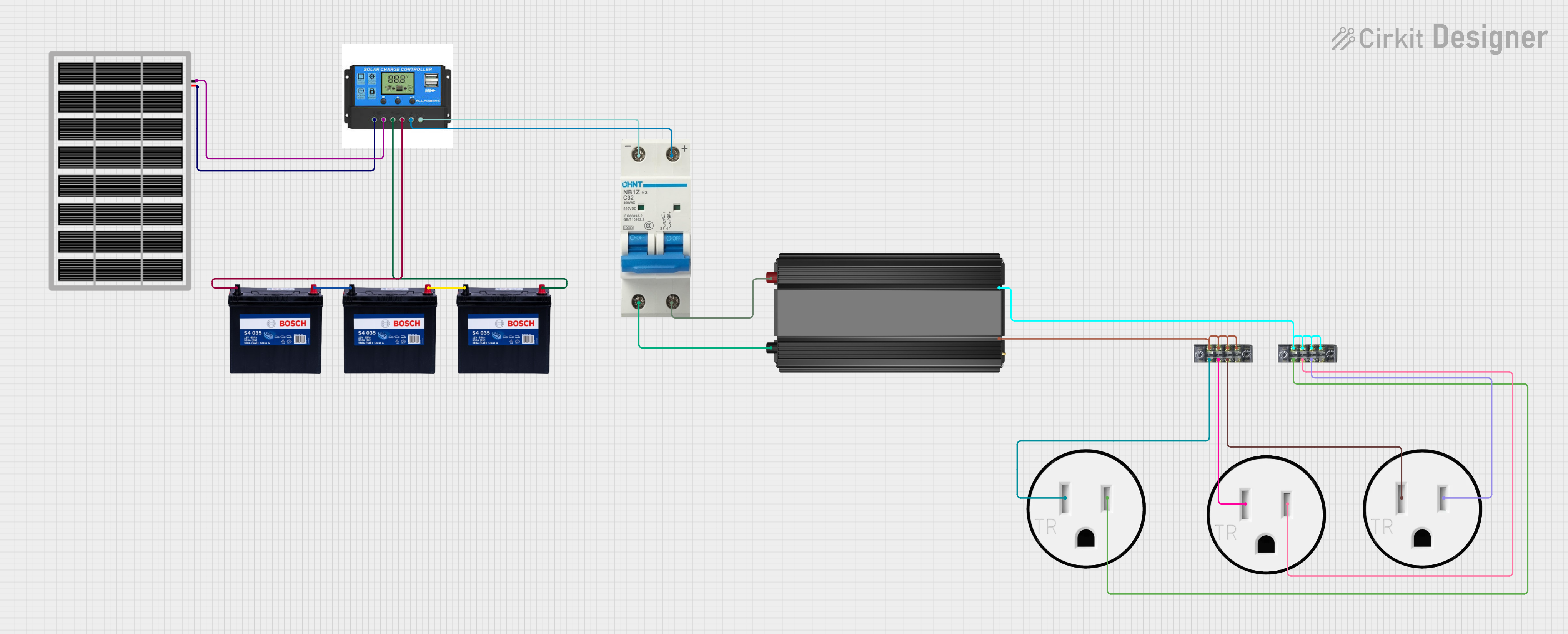
Common Applications and Use Cases
- Solar power systems to protect photovoltaic (PV) circuits
- Battery banks and energy storage systems
- Electric vehicle (EV) charging stations
- DC motor protection in industrial applications
- Low-voltage DC distribution panels
Technical Specifications
The following table outlines the key technical details of the DC Breaker 20A:
| Parameter | Specification |
|---|---|
| Rated Current | 20A |
| Rated Voltage | 12V DC, 24V DC, or 48V DC |
| Breaking Capacity | 6 kA (at rated voltage) |
| Trip Mechanism | Thermal-magnetic |
| Operating Temperature | -20°C to +70°C |
| Mounting Type | DIN rail or panel mount |
| Terminal Type | Screw terminals |
| Dimensions (L x W x H) | 90mm x 18mm x 75mm |
| Compliance Standards | IEC 60947-2, UL 1077 |
Pin Configuration and Descriptions
The DC Breaker 20A does not have traditional pins but instead features screw terminals for input and output connections. The terminal configuration is as follows:
| Terminal Label | Description |
|---|---|
| Line (L) | Connects to the positive side of the DC power source |
| Load (OUT) | Connects to the positive side of the load |
| Ground (optional) | For grounding the breaker housing (if applicable) |
Usage Instructions
How to Use the DC Breaker 20A in a Circuit
- Determine the Voltage and Current Requirements: Ensure the breaker is rated for the voltage and current of your DC circuit. The maximum current should not exceed 20A.
- Mount the Breaker: Install the breaker on a DIN rail or panel mount, depending on your setup.
- Connect the Terminals:
- Connect the positive terminal of the DC power source to the
Line (L)terminal. - Connect the positive terminal of the load to the
Load (OUT)terminal. - If applicable, connect the ground terminal to the system ground.
- Connect the positive terminal of the DC power source to the
- Verify Connections: Double-check all connections to ensure they are secure and correctly polarized.
- Power On the Circuit: Turn on the DC power source. The breaker will automatically trip if an overload or short circuit occurs.
Important Considerations and Best Practices
- Do Not Exceed Ratings: Ensure the current and voltage do not exceed the breaker's specifications.
- Use Proper Wire Gauge: Use wires with an appropriate gauge to handle the current without overheating.
- Test the Breaker Regularly: Periodically test the breaker's trip mechanism to ensure it functions correctly.
- Avoid Reverse Polarity: Connecting the breaker with reversed polarity may damage the device or compromise its performance.
- Ambient Temperature: Install the breaker in an environment within its operating temperature range to avoid nuisance tripping.
Example: Using the DC Breaker 20A with an Arduino UNO
If you are using the DC Breaker 20A in a circuit powered by an Arduino UNO, ensure the breaker is placed between the DC power source and the Arduino's input voltage pin. Below is an example of how to monitor the breaker's status using a digital input pin on the Arduino:
// Arduino code to monitor the status of a DC Breaker
const int breakerPin = 2; // Digital pin connected to the breaker's status output
const int ledPin = 13;    // Built-in LED to indicate breaker status

void setup() {
  pinMode(breakerPin, INPUT_PULLUP); // Configure breakerPin as input with pull-up
  pinMode(ledPin, OUTPUT);           // Configure ledPin as output
  Serial.begin(9600);                // Initialize serial communication
}

void loop() {
  int breakerStatus = digitalRead(breakerPin); // Read the breaker's status

  if (breakerStatus == HIGH) {
    // Breaker is in normal (closed) state
    digitalWrite(ledPin, HIGH); // Turn on LED
    Serial.println("Breaker is ON (closed).");
  } else {
    // Breaker is tripped (open) state
    digitalWrite(ledPin, LOW);  // Turn off LED
    Serial.println("Breaker is OFF (tripped).");
  }

  delay(500); // Wait for 500ms before checking again
}
Note: The breaker must have a status output terminal for this code to work. If the breaker does not provide a status signal, this example is not applicable.
Troubleshooting and FAQs
Common Issues and Solutions
Breaker Trips Frequently:
- Cause: Overload or short circuit in the connected circuit.
- Solution: Check the load current and ensure it does not exceed 20A. Inspect the circuit for short circuits or faulty components.
Breaker Does Not Trip During Fault:
- Cause: Faulty breaker or incorrect installation.
- Solution: Verify the connections and test the breaker's trip mechanism. Replace the breaker if necessary.
Breaker Overheats:
- Cause: Loose connections or ambient temperature exceeding the specified range.
- Solution: Tighten all connections and ensure proper ventilation around the breaker.
No Power to the Load:
- Cause: Breaker is in the tripped state or not properly connected.
- Solution: Reset the breaker and verify the input and output connections.
FAQs
Q1: Can the DC Breaker 20A be used in AC circuits?
A1: No, this breaker is specifically designed for DC circuits. Using it in AC circuits may result in improper operation or damage.
Q2: How do I reset the breaker after it trips?
A2: To reset the breaker, switch it to the "OFF" position and then back to the "ON" position.
Q3: Can I use this breaker in a 60V DC system?
A3: No, the maximum rated voltage for this breaker is 48V DC. Using it in a higher voltage system may compromise safety and performance.
Q4: Is the breaker polarity-sensitive?
A4: Yes, the breaker must be connected with the correct polarity. Reversing the polarity may damage the device or cause it to malfunction.