How to Use AHT20+BMP280: Examples, Pinouts, and Specs
AHT20 + BMP280 Sensor Module Documentation
1. Introduction
The AHT20 + BMP280 Sensor Module is a versatile environmental sensing device that combines two powerful sensors in a single module. The AHT20 is a high-precision temperature and humidity sensor, while the BMP280 is a barometric pressure sensor capable of measuring atmospheric pressure and altitude. Together, they provide a comprehensive solution for environmental monitoring applications.
Common Applications:
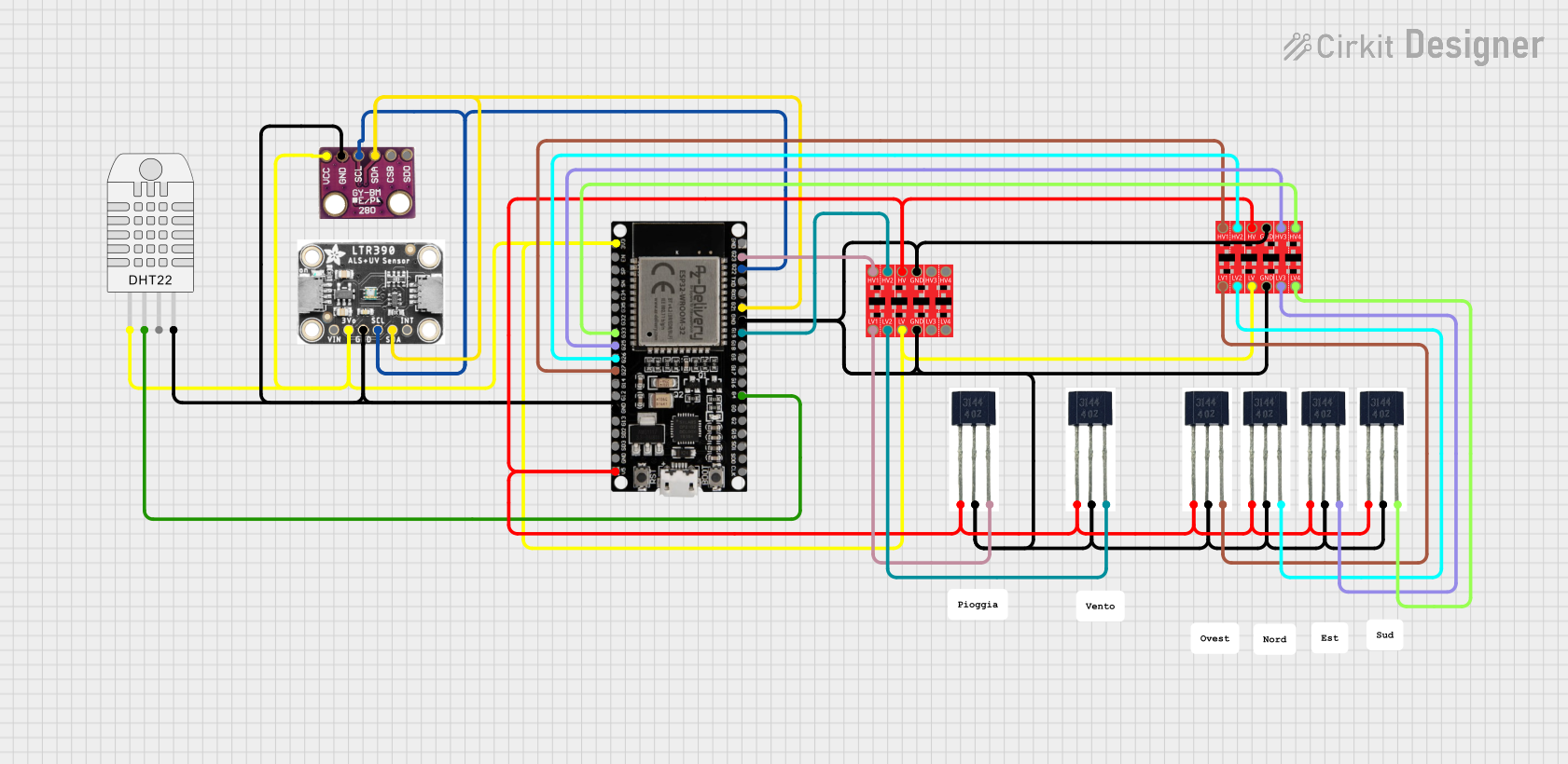
- Weather stations
- IoT (Internet of Things) devices
- HVAC (Heating, Ventilation, and Air Conditioning) systems
- Altitude measurement for drones and other vehicles
- Environmental data logging
- Smart agriculture systems
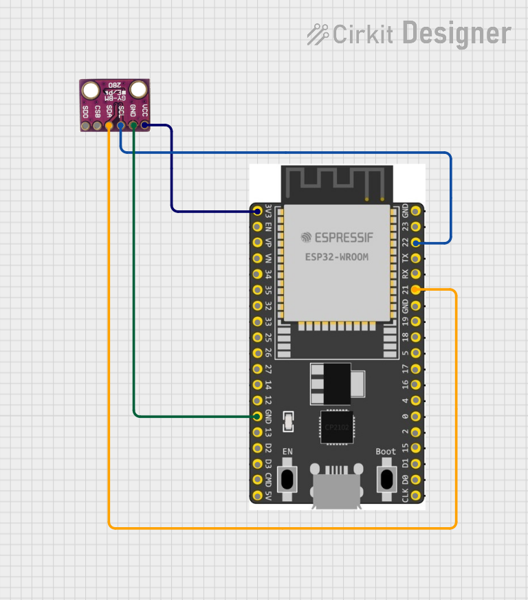
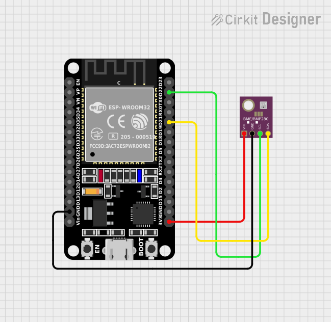
This module is commonly used with microcontrollers like the Arduino UNO, ESP32, and Raspberry Pi due to its I2C communication interface, which simplifies integration.
2. Technical Specifications
AHT20 Sensor Specifications:
| Parameter | Value |
|---|---|
| Supply Voltage | 2.0V to 5.5V |
| Operating Current | 0.25 mA (average) |
| Temperature Range | -40°C to 85°C |
| Temperature Accuracy | ±0.3°C |
| Humidity Range | 0% to 100% RH |
| Humidity Accuracy | ±2% RH |
| Communication Protocol | I2C |
| I2C Address | 0x38 |
BMP280 Sensor Specifications:
| Parameter | Value |
|---|---|
| Supply Voltage | 1.71V to 3.6V |
| Operating Current | 2.7 µA (in normal mode) |
| Pressure Range | 300 hPa to 1100 hPa |
| Pressure Accuracy | ±1 hPa |
| Temperature Range | -40°C to 85°C |
| Temperature Accuracy | ±1°C |
| Communication Protocol | I2C or SPI |
| I2C Address | 0x76 (default) or 0x77 (optional) |
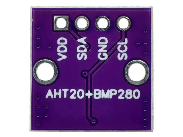
Pin Configuration:
| Pin | Description |
|---|---|
| VCC | Power supply (3.3V or 5V) |
| GND | Ground |
| SDA | I2C data line |
| SCL | I2C clock line |
3. Usage Instructions
Connecting the AHT20 + BMP280 Module to an Arduino UNO:
Wiring:
- Connect the module's
VCCpin to the Arduino's5Vpin. - Connect the
GNDpin to the Arduino'sGND. - Connect the
SDApin to the Arduino'sA4pin (I2C data line). - Connect the
SCLpin to the Arduino'sA5pin (I2C clock line).
- Connect the module's
Install Required Libraries:
- Install the
Adafruit_AHTX0library for the AHT20 sensor. - Install the
Adafruit_BMP280library for the BMP280 sensor. - These libraries can be installed via the Arduino IDE Library Manager.
- Install the
Sample Code: Below is an example Arduino sketch to read temperature, humidity, and pressure data from the AHT20 and BMP280 sensors.
#include <Wire.h>
#include <Adafruit_AHTX0.h>  // Library for AHT20
#include <Adafruit_BMP280.h> // Library for BMP280

// Create sensor objects
Adafruit_AHTX0 aht;
Adafruit_BMP280 bmp;

void setup() {
  Serial.begin(9600);
  while (!Serial); // Wait for Serial Monitor to open

  // Initialize AHT20 sensor
  if (!aht.begin()) {
    Serial.println("Failed to initialize AHT20 sensor!");
    while (1);
  }
  Serial.println("AHT20 sensor initialized.");

  // Initialize BMP280 sensor
  if (!bmp.begin(0x76)) { // Default I2C address for BMP280
    Serial.println("Failed to initialize BMP280 sensor!");
    while (1);
  }
  Serial.println("BMP280 sensor initialized.");
}

void loop() {
  // Read data from AHT20
  sensors_event_t humidity, temp;
  aht.getEvent(&humidity, &temp);

  // Read data from BMP280
  float pressure = bmp.readPressure() / 100.0F; // Convert to hPa
  float altitude = bmp.readAltitude(1013.25);  // Adjust sea level pressure as needed

  // Print sensor data to Serial Monitor
  Serial.print("Temperature (AHT20): ");
  Serial.print(temp.temperature);
  Serial.println(" °C");

  Serial.print("Humidity (AHT20): ");
  Serial.print(humidity.relative_humidity);
  Serial.println(" %");

  Serial.print("Pressure (BMP280): ");
  Serial.print(pressure);
  Serial.println(" hPa");

  Serial.print("Altitude (BMP280): ");
  Serial.print(altitude);
  Serial.println(" m");

  Serial.println("-----------------------------");
  delay(2000); // Wait 2 seconds before next reading
}
Important Considerations:
- Ensure proper pull-up resistors (typically 4.7kΩ) are connected to the
SDAandSCLlines if not already included on the module. - Use a stable power supply to avoid noise in sensor readings.
- If using multiple I2C devices, ensure they have unique addresses or use an I2C multiplexer.
4. Troubleshooting and FAQs
Common Issues and Solutions:
Problem: The sensors are not detected by the Arduino.
- Solution: Check the wiring and ensure the
SDAandSCLlines are correctly connected. Verify the I2C addresses of the sensors.
- Solution: Check the wiring and ensure the
Problem: Incorrect or fluctuating readings.
- Solution: Ensure a stable power supply and avoid placing the sensors near heat sources or high-humidity areas.
Problem: Compilation errors when uploading the code.
- Solution: Ensure the required libraries (
Adafruit_AHTX0andAdafruit_BMP280) are installed and up to date.
- Solution: Ensure the required libraries (
Problem: Altitude readings are inaccurate.
- Solution: Adjust the sea-level pressure value in the code (
1013.25 hPaby default) to match your local atmospheric pressure.
- Solution: Adjust the sea-level pressure value in the code (
FAQs:
Q1: Can I use this module with a 3.3V microcontroller?
A1: Yes, the module supports both 3.3V and 5V logic levels.
Q2: Can I use SPI communication for the BMP280?
A2: Yes, the BMP280 supports SPI, but the AHT20 only supports I2C. For simplicity, use I2C for both sensors.
Q3: How do I extend the I2C cable length?
A3: Use shielded cables and lower the I2C clock speed to reduce noise and signal degradation.
This documentation provides a comprehensive guide to using the AHT20 + BMP280 sensor module. Whether you're a beginner or an experienced user, this guide will help you integrate the module into your projects effectively.
Explore Projects Built with AHT20+BMP280
Explore Projects Built with AHT20+BMP280