How to Use OXY-LC Interface Board: Examples, Pinouts, and Specs
Introduction
The OXY-LC Interface Board (OXY-LC-485), manufactured by SST Sensing, is a specialized circuit board designed to facilitate communication between the OXY-LC oxygen sensor and other electronic systems. It enables seamless data transfer and control functions, making it an essential component for integrating oxygen sensors into a variety of applications.
Explore Projects Built with OXY-LC Interface Board
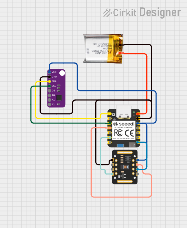
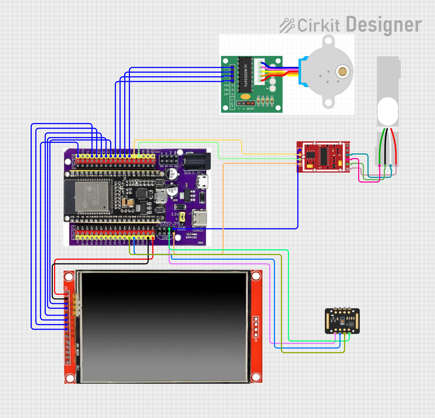

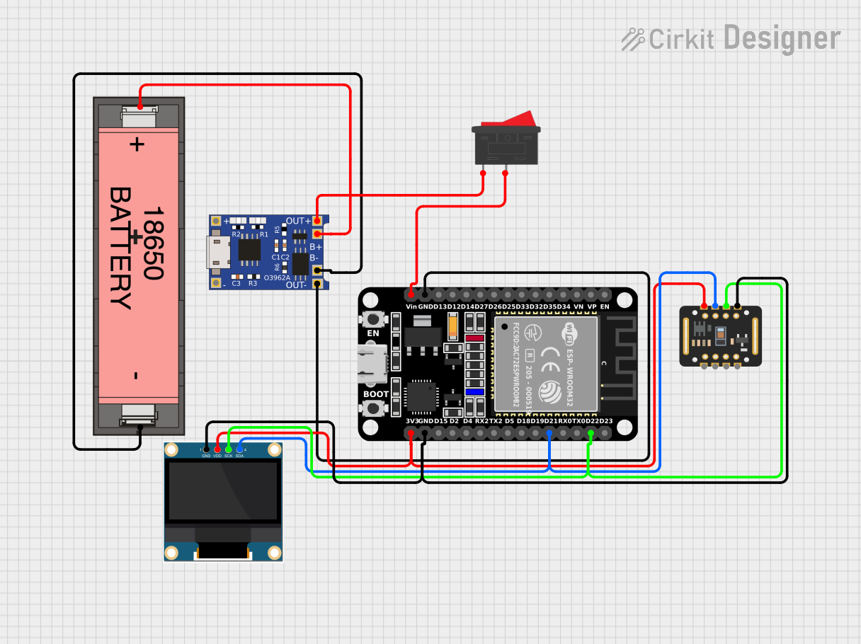
Explore Projects Built with OXY-LC Interface Board
Common Applications and Use Cases
- Industrial process control and monitoring
- Environmental monitoring systems
- Medical equipment requiring oxygen level measurement
- Laboratory instrumentation
- Automotive and aerospace oxygen sensing
Technical Specifications
The OXY-LC Interface Board is designed to provide reliable communication and control for the OXY-LC oxygen sensor. Below are the key technical details:
General Specifications
| Parameter | Value |
|---|---|
| Manufacturer | SST Sensing |
| Part Number | OXY-LC-485 |
| Communication Protocol | RS-485 |
| Supply Voltage | 5 V DC |
| Operating Temperature | -20°C to +60°C |
| Dimensions | 50 mm x 25 mm x 10 mm |
| Mounting Type | PCB Mount |
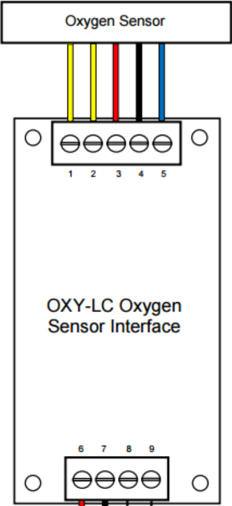
Pin Configuration and Descriptions
The OXY-LC Interface Board features a straightforward pinout for easy integration. Below is the pin configuration:
| Pin Number | Pin Name | Description |
|---|---|---|
| 1 | VCC | Power supply input (5 V DC) |
| 2 | GND | Ground connection |
| 3 | TX+ | RS-485 differential transmit line (positive) |
| 4 | TX- | RS-485 differential transmit line (negative) |
| 5 | RX+ | RS-485 differential receive line (positive) |
| 6 | RX- | RS-485 differential receive line (negative) |
| 7 | SENSOR_IN | Input connection for the OXY-LC oxygen sensor |
| 8 | CONFIG | Configuration pin for setting communication parameters (e.g., baud rate) |
Usage Instructions
The OXY-LC Interface Board is designed for easy integration into electronic systems. Follow the steps below to use the board effectively:
Connecting the OXY-LC Interface Board
- Power Supply: Connect the
VCCpin to a 5 V DC power source and theGNDpin to ground. - Sensor Connection: Attach the OXY-LC oxygen sensor to the
SENSOR_INpin. - RS-485 Communication:
- Connect the
TX+andTX-pins to the RS-485 transmit lines of your system. - Connect the
RX+andRX-pins to the RS-485 receive lines of your system.
- Connect the
- Configuration: Use the
CONFIGpin to set communication parameters, such as baud rate, if required.
Important Considerations and Best Practices
- Ensure the power supply voltage is stable and within the specified range (5 V DC).
- Use proper termination resistors for RS-485 communication lines to minimize signal reflections.
- Avoid exposing the board to temperatures outside the operating range (-20°C to +60°C).
- Keep the board away from sources of electromagnetic interference (EMI) to ensure reliable communication.
- Verify the sensor is securely connected to the
SENSOR_INpin to avoid data loss or inaccuracies.
Example: Connecting to an Arduino UNO
The OXY-LC Interface Board can be connected to an Arduino UNO for data acquisition and processing. Below is an example code snippet for reading data from the board:
#include <SoftwareSerial.h>

// Define RS-485 communication pins
#define RX_PIN 10  // Arduino pin connected to RX+ of OXY-LC Interface Board
#define TX_PIN 11  // Arduino pin connected to TX+ of OXY-LC Interface Board

// Initialize SoftwareSerial for RS-485 communication
SoftwareSerial rs485Serial(RX_PIN, TX_PIN);

void setup() {
  // Start serial communication with the OXY-LC Interface Board
  rs485Serial.begin(9600); // Set baud rate to 9600 (adjust if necessary)
  Serial.begin(9600);      // Start serial monitor for debugging

  Serial.println("OXY-LC Interface Board Communication Initialized");
}

void loop() {
  // Check if data is available from the OXY-LC Interface Board
  if (rs485Serial.available()) {
    String oxygenData = rs485Serial.readString(); // Read data from the board
    Serial.print("Oxygen Sensor Data: ");
    Serial.println(oxygenData); // Print data to the serial monitor
  }

  delay(1000); // Wait for 1 second before reading again
}
Note: Ensure the RS-485 transceiver module is used between the Arduino and the OXY-LC Interface Board to handle differential signaling.
Troubleshooting and FAQs
Common Issues and Solutions
No Data Received from the Board
- Cause: Incorrect wiring or loose connections.
- Solution: Verify all connections, especially the RS-485 lines and the sensor input.
Communication Errors
- Cause: Mismatched baud rate or improper termination resistors.
- Solution: Check the baud rate settings and ensure proper termination resistors are in place.
Sensor Data is Inaccurate
- Cause: Faulty sensor connection or environmental interference.
- Solution: Ensure the sensor is securely connected and shield the board from EMI.
Board Overheating
- Cause: Operating outside the specified temperature range.
- Solution: Ensure the board is used within the -20°C to +60°C range.
FAQs
Q: Can the OXY-LC Interface Board be used with other sensors?
A: No, the board is specifically designed for use with the OXY-LC oxygen sensor.
Q: What is the maximum communication distance for RS-485?
A: RS-485 supports communication distances up to 1200 meters, depending on the baud rate and cable quality.
Q: How do I change the baud rate of the board?
A: Use the CONFIG pin to set the desired baud rate. Refer to the manufacturer's documentation for detailed instructions.
Q: Is the board compatible with 3.3 V systems?
A: No, the board requires a 5 V DC power supply for proper operation. Use a level shifter if interfacing with 3.3 V systems.