How to Use A7670E LTEGNSS Cat-1 Module: Examples, Pinouts, and Specs
Introduction
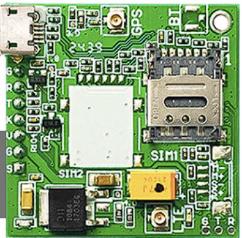
The A7670E is a compact LTE Cat-1 module manufactured by SIMCom Wireless Solutions. It supports high-speed data transmission and GNSS (Global Navigation Satellite System) positioning, making it an ideal solution for IoT (Internet of Things) applications. With its robust design and versatile functionality, the A7670E is well-suited for applications such as smart metering, asset tracking, fleet management, and industrial automation.
Explore Projects Built with A7670E LTEGNSS Cat-1 Module


Explore Projects Built with A7670E LTEGNSS Cat-1 Module
Common Applications and Use Cases
- Smart Metering: Enables real-time data transmission for utility monitoring.
- Asset Tracking: Provides precise location data for logistics and supply chain management.
- Fleet Management: Facilitates vehicle tracking and communication.
- Industrial Automation: Ensures reliable connectivity for remote monitoring and control.
- Wearable Devices: Supports compact designs with low power consumption.
Technical Specifications
Key Technical Details
| Parameter | Specification |
|---|---|
| Manufacturer | SIMCom Wireless Solutions |
| Part Number | A7670E |
| Cellular Technology | LTE Cat-1 |
| Frequency Bands | LTE: B1/B3/B5/B7/B8/B20/B28; GSM: 900/1800 MHz |
| Data Rate | LTE: 10 Mbps (DL) / 5 Mbps (UL) |
| GNSS Support | GPS, GLONASS, BeiDou, Galileo, QZSS |
| Operating Voltage | 3.3V to 4.3V (Typical: 3.8V) |
| Power Consumption | Idle: ~1.2 mA; Active: ~500 mA (LTE Tx) |
| Operating Temperature | -40°C to +85°C |
| Dimensions | 24.0 mm × 24.0 mm × 2.4 mm |
| Interface | UART, USB 2.0, GPIO, I2C, SPI, ADC |
| Certifications | CE, FCC, RoHS |
Pin Configuration and Descriptions
The A7670E module has a total of 42 pins. Below is a summary of the key pins:
| Pin Number | Pin Name | Description |
|---|---|---|
| 1 | VCC | Power supply input (3.3V to 4.3V) |
| 2 | GND | Ground |
| 3 | TXD | UART Transmit Data |
| 4 | RXD | UART Receive Data |
| 5 | GNSS_TXD | GNSS UART Transmit Data |
| 6 | GNSS_RXD | GNSS UART Receive Data |
| 7 | USB_DP | USB Data Positive |
| 8 | USB_DM | USB Data Negative |
| 9 | RESET | Reset input (active low) |
| 10 | PWRKEY | Power-on key (active low) |
| 11 | ADC_IN | Analog-to-Digital Converter input |
| 12 | GPIO1 | General Purpose Input/Output |
| 13 | GPIO2 | General Purpose Input/Output |
| 14 | NET_STATUS | Network status indicator |
| 15 | SIM_DET | SIM card detection |
For a complete pinout, refer to the official datasheet provided by SIMCom Wireless Solutions.
Usage Instructions
How to Use the A7670E in a Circuit
- Power Supply: Connect the VCC pin to a stable 3.8V power source and GND to ground. Ensure the power supply can handle peak currents of up to 2A during LTE transmission.
- UART Communication: Connect the TXD and RXD pins to a microcontroller or host device for serial communication. Use a baud rate of 115200 bps (default).
- GNSS Functionality: To enable GNSS, connect the GNSS_TXD and GNSS_RXD pins to the host device. An external GNSS antenna is required for optimal performance.
- Power-On Sequence: Pull the PWRKEY pin low for at least 1 second to power on the module.
- SIM Card Interface: Insert a standard 1.8V/3.0V SIM card into the SIM card slot. Use the SIM_DET pin to detect the presence of a SIM card.
- Antenna Connections: Connect LTE and GNSS antennas to the respective antenna ports. Ensure proper impedance matching (50Ω).
Important Considerations and Best Practices
- Power Supply Stability: Use decoupling capacitors (e.g., 100 µF and 0.1 µF) near the VCC pin to minimize voltage fluctuations.
- Antenna Placement: Place antennas away from noise sources and ensure a clear line of sight for GNSS signals.
- Firmware Updates: Regularly update the module's firmware to ensure compatibility and performance.
- ESD Protection: Implement ESD protection on all external interfaces to prevent damage.
Example: Connecting A7670E to Arduino UNO
Below is an example of how to interface the A7670E module with an Arduino UNO for basic communication:
Circuit Connections
| A7670E Pin | Arduino UNO Pin |
|---|---|
| TXD | D2 (RX) |
| RXD | D3 (TX) |
| GND | GND |
| VCC | 3.3V (External Power Supply) |
Arduino Code
#include <SoftwareSerial.h>

// Define RX and TX pins for SoftwareSerial
SoftwareSerial A7670E(2, 3); // RX = Pin 2, TX = Pin 3

void setup() {
  // Initialize serial communication with the A7670E module
  A7670E.begin(115200);
  Serial.begin(9600); // For debugging via Serial Monitor

  // Send initialization command to the module
  A7670E.println("AT"); // Basic AT command to check communication
}

void loop() {
  // Check if the module sends any data
  if (A7670E.available()) {
    String response = A7670E.readString();
    Serial.println("Module Response: " + response);
  }

  // Check if user sends data via Serial Monitor
  if (Serial.available()) {
    String command = Serial.readString();
    A7670E.println(command); // Forward command to the module
  }
}
Troubleshooting and FAQs
Common Issues and Solutions
Module Not Powering On
- Cause: Insufficient power supply or incorrect PWRKEY usage.
- Solution: Ensure the power supply provides at least 2A peak current. Pull the PWRKEY pin low for at least 1 second.
No Response to AT Commands
- Cause: Incorrect UART connections or baud rate mismatch.
- Solution: Verify TXD and RXD connections. Ensure the baud rate is set to 115200 bps.
GNSS Not Acquiring Satellites
- Cause: Poor antenna placement or interference.
- Solution: Place the GNSS antenna in an open area with a clear view of the sky. Avoid placing it near electronic noise sources.
SIM Card Not Detected
- Cause: Improper SIM card insertion or unsupported SIM voltage.
- Solution: Ensure the SIM card is properly seated and supports 1.8V/3.0V operation.
FAQs
Q: Can the A7670E module operate on 5V logic levels?
A: No, the module operates on 3.3V logic levels. Use a level shifter if interfacing with 5V devices.Q: Does the module support voice calls?
A: Yes, the A7670E supports voice calls over LTE networks.Q: How can I update the firmware?
A: Firmware updates can be performed via the USB interface using SIMCom's official tools.Q: What is the maximum GNSS accuracy?
A: The module provides positioning accuracy of up to 2.5 meters under ideal conditions.
This concludes the documentation for the A7670E LTEGNSS Cat-1 Module. For further details, refer to the official datasheet and user manual provided by SIMCom Wireless Solutions.