How to Use ESP-32S NodeMCU: Examples, Pinouts, and Specs
Introduction
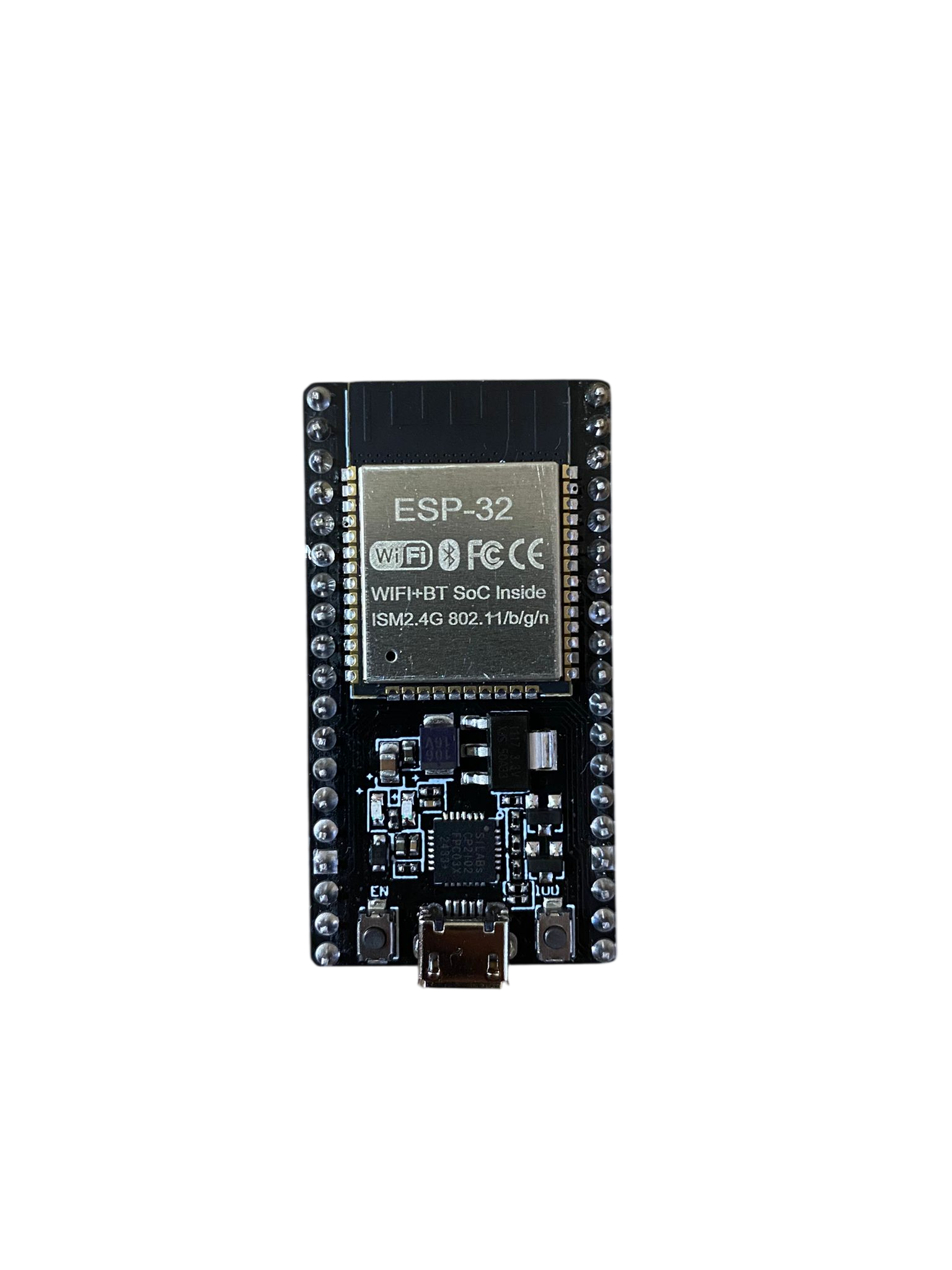
The ESP-32S NodeMCU is a powerful microcontroller board developed by NodeMCU, featuring the ESP-32S chip. It is designed for IoT (Internet of Things) applications and rapid prototyping, offering built-in Wi-Fi and Bluetooth capabilities. This versatile board is widely used in smart home devices, wearable electronics, and industrial automation projects due to its high performance, low power consumption, and extensive connectivity options.
Explore Projects Built with ESP-32S NodeMCU
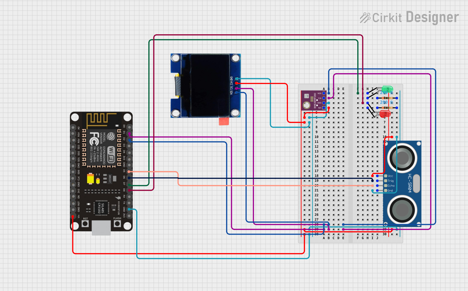
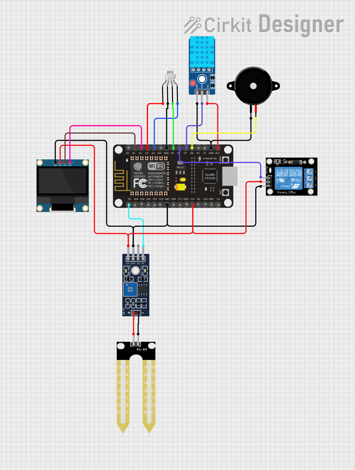
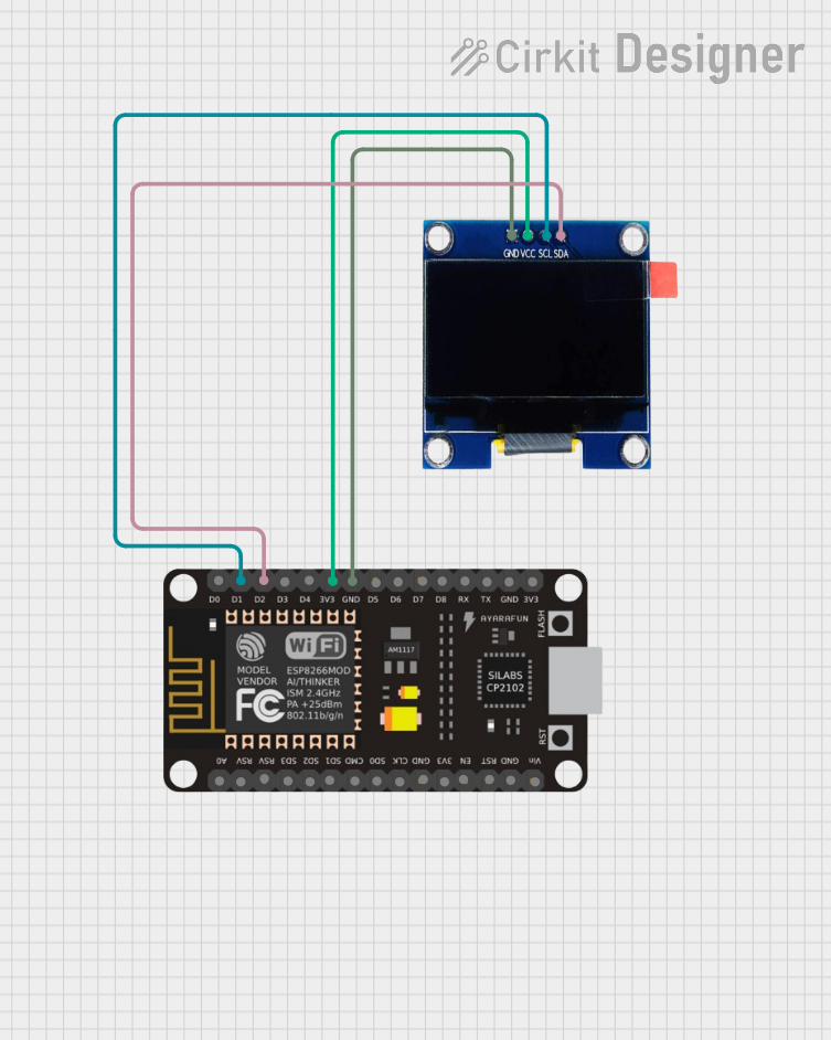
Explore Projects Built with ESP-32S NodeMCU
Common Applications and Use Cases
- IoT devices (e.g., smart home systems, environmental monitoring)
- Wireless sensor networks
- Wearable electronics
- Robotics and automation
- Prototyping and educational projects
- Bluetooth-enabled applications (e.g., BLE beacons, remote controls)
Technical Specifications
The ESP-32S NodeMCU is equipped with robust hardware and connectivity features. Below are its key technical specifications:
Key Technical Details
- Microcontroller: ESP-32S (dual-core Xtensa LX6 processor)
- Clock Speed: Up to 240 MHz
- Flash Memory: 4 MB
- SRAM: 520 KB
- Wi-Fi: IEEE 802.11 b/g/n (2.4 GHz)
- Bluetooth: Bluetooth 4.2 and BLE (Bluetooth Low Energy)
- Operating Voltage: 3.3V
- Input Voltage: 5V (via USB) or 7-12V (via VIN pin)
- GPIO Pins: 30 (multipurpose, including ADC, DAC, PWM, I2C, SPI, UART)
- ADC Channels: 18 (12-bit resolution)
- DAC Channels: 2
- Power Consumption: Ultra-low power consumption in deep sleep mode (~10 µA)
- Dimensions: 58 mm x 25.5 mm
Pin Configuration and Descriptions
The ESP-32S NodeMCU has a total of 30 GPIO pins, each with multiple functions. Below is the pinout description:
| Pin | Function | Description |
|---|---|---|
| VIN | Power Input | Input voltage (7-12V) for powering the board. |
| 3V3 | Power Output | Provides 3.3V output for external components. |
| GND | Ground | Ground connection. |
| EN | Enable | Enables or disables the chip. Active high. |
| GPIO0 | General Purpose I/O, Boot Pin | Used for boot mode selection during programming. |
| GPIO1 | UART TX | UART transmit pin. |
| GPIO3 | UART RX | UART receive pin. |
| GPIO12 | ADC, Touch Sensor | Analog input or touch sensor input. |
| GPIO13 | ADC, PWM, Touch Sensor | Analog input, PWM output, or touch sensor input. |
| GPIO14 | ADC, PWM, Touch Sensor | Analog input, PWM output, or touch sensor input. |
| GPIO15 | ADC, PWM, Touch Sensor | Analog input, PWM output, or touch sensor input. |
| GPIO16 | GPIO | General-purpose digital I/O. |
| GPIO17 | GPIO | General-purpose digital I/O. |
| GPIO18 | SPI CLK | SPI clock pin. |
| GPIO19 | SPI MISO | SPI Master-In-Slave-Out pin. |
| GPIO21 | I2C SDA | I2C data line. |
| GPIO22 | I2C SCL | I2C clock line. |
| GPIO23 | SPI MOSI | SPI Master-Out-Slave-In pin. |
| GPIO25 | DAC, PWM | Digital-to-Analog Converter or PWM output. |
| GPIO26 | DAC, PWM | Digital-to-Analog Converter or PWM output. |
| GPIO27 | ADC, PWM | Analog input or PWM output. |
| GPIO32 | ADC, Touch Sensor | Analog input or touch sensor input. |
| GPIO33 | ADC, Touch Sensor | Analog input or touch sensor input. |
| GPIO34 | ADC | Analog input (input-only pin). |
| GPIO35 | ADC | Analog input (input-only pin). |
| GPIO36 | ADC | Analog input (input-only pin). |
| GPIO39 | ADC | Analog input (input-only pin). |
Usage Instructions
How to Use the ESP-32S NodeMCU in a Circuit
Powering the Board:
- Use a micro-USB cable to power the board via the USB port.
- Alternatively, supply 7-12V to the VIN pin or 3.3V to the 3V3 pin.
Programming the Board:
- Install the Arduino IDE and add the ESP32 board support package.
- Connect the board to your computer via USB.
- Select the correct board (
ESP32 Dev Module) and port in the Arduino IDE. - Write or upload your code to the board.
Connecting Peripherals:
- Use the GPIO pins to connect sensors, actuators, or other peripherals.
- Ensure that the voltage levels of connected devices are compatible with the 3.3V logic of the ESP-32S.
Wi-Fi and Bluetooth Setup:
- Use the built-in libraries (
WiFi.handBluetoothSerial.h) to configure wireless communication.
- Use the built-in libraries (
Important Considerations and Best Practices
- Avoid supplying more than 3.3V to the GPIO pins to prevent damage.
- Use level shifters when interfacing with 5V devices.
- Ensure proper grounding for stable operation.
- Use decoupling capacitors to reduce noise in power supply lines.
- When using Wi-Fi or Bluetooth, ensure a stable power source to avoid resets.
Example Code for Arduino IDE
The following example demonstrates how to connect the ESP-32S NodeMCU to a Wi-Fi network and blink an LED:
#include <WiFi.h> // Include the WiFi library

const char* ssid = "Your_SSID";       // Replace with your Wi-Fi SSID
const char* password = "Your_Password"; // Replace with your Wi-Fi password
const int ledPin = 2;                 // Built-in LED pin (GPIO2)

void setup() {
  pinMode(ledPin, OUTPUT);            // Set LED pin as output
  Serial.begin(115200);               // Initialize serial communication
  Serial.println("Connecting to Wi-Fi...");

  WiFi.begin(ssid, password);         // Connect to Wi-Fi
  while (WiFi.status() != WL_CONNECTED) {
    delay(500);
    Serial.print(".");
  }
  Serial.println("\nWi-Fi connected!");
  Serial.print("IP Address: ");
  Serial.println(WiFi.localIP());     // Print the IP address
}

void loop() {
  digitalWrite(ledPin, HIGH);         // Turn the LED on
  delay(1000);                        // Wait for 1 second
  digitalWrite(ledPin, LOW);          // Turn the LED off
  delay(1000);                        // Wait for 1 second
}
Troubleshooting and FAQs
Common Issues and Solutions
Board Not Detected by Computer:
- Ensure the USB cable is functional and supports data transfer.
- Install the correct USB-to-serial driver for the ESP-32S.
Wi-Fi Connection Fails:
- Double-check the SSID and password.
- Ensure the Wi-Fi network is within range and operational.
Program Upload Fails:
- Verify the correct board and port are selected in the Arduino IDE.
- Press and hold the
BOOTbutton on the board while uploading the code.
Random Resets or Instability:
- Use a stable power source with sufficient current (at least 500 mA).
- Add capacitors to the power supply lines to reduce noise.
FAQs
Q: Can the ESP-32S NodeMCU operate on battery power?
- A: Yes, it can be powered using a LiPo battery connected to the VIN pin.
Q: How many devices can connect to the ESP-32S via Bluetooth?
- A: The ESP-32S supports up to 7 simultaneous Bluetooth connections.
Q: Can I use the ESP-32S for deep sleep applications?
- A: Yes, the ESP-32S supports ultra-low power deep sleep mode, consuming ~10 µA.
Q: Is the ESP-32S compatible with 5V logic?
- A: No, the ESP-32S operates on 3.3V logic. Use level shifters for 5V devices.