How to Use DS18B20: Examples, Pinouts, and Specs
Introduction
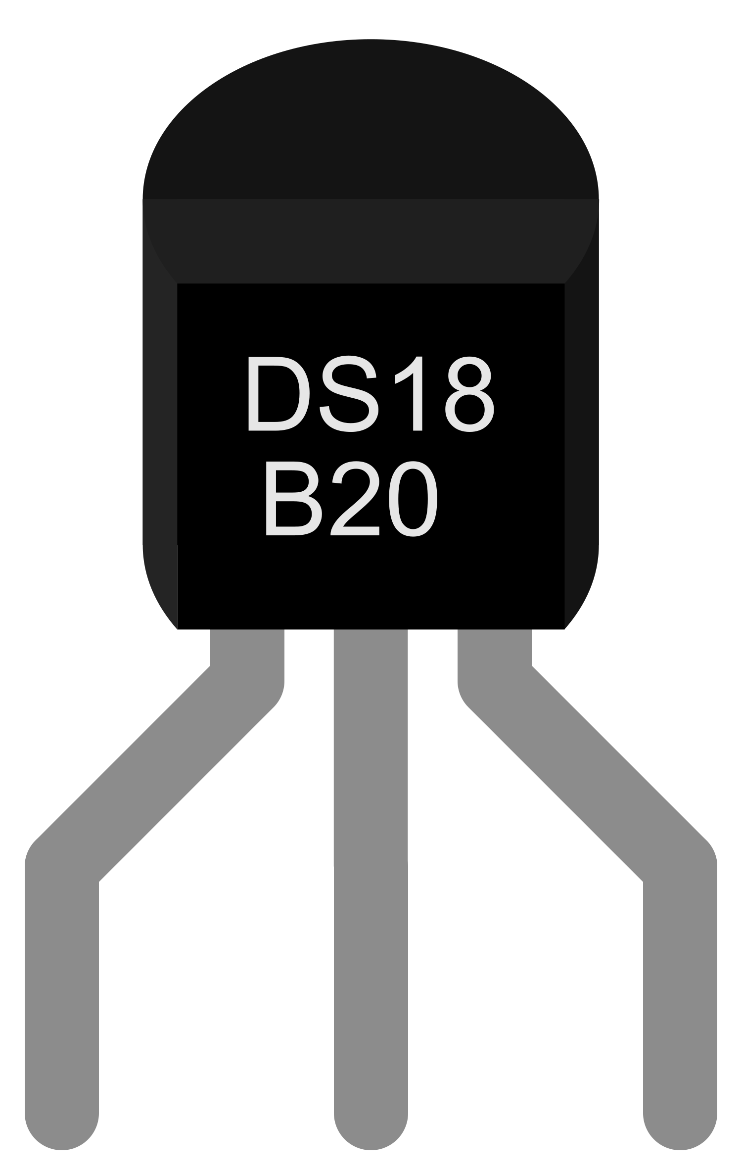
The DS18B20 is a precision digital temperature sensor that offers a convenient one-wire interface, allowing for easy integration with microcontrollers such as the Arduino UNO. It is widely used in various applications, including environmental temperature monitoring, HVAC systems, and consumer electronics. The sensor's unique ability to operate over a wide temperature range and its small footprint make it ideal for embedded systems.
Explore Projects Built with DS18B20
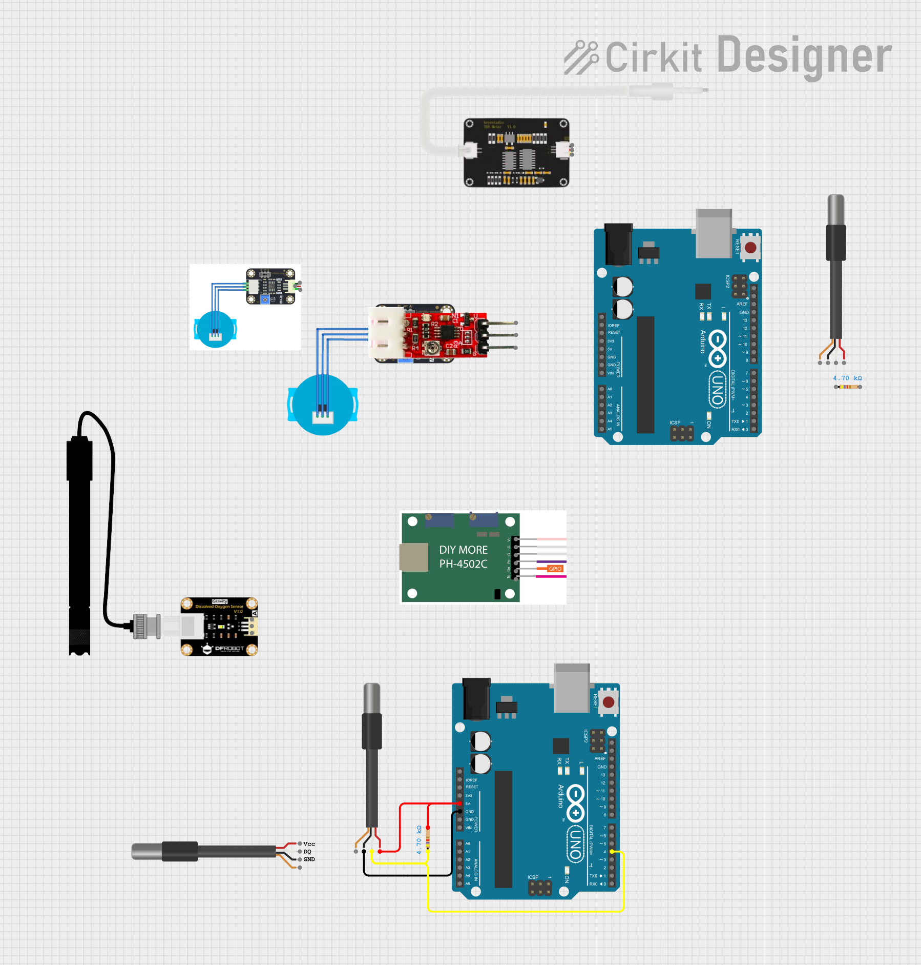
Explore Projects Built with DS18B20
Technical Specifications
Key Features
- Temperature Range: -55°C to +125°C (-67°F to +257°F)
- Accuracy: ±0.5°C accuracy from -10°C to +85°C
- Resolution: Selectable from 9 to 12 bits
- Supply Voltage: 3.0V to 5.5V
- Current: 1mA active, 1µA standby
Pin Configuration
| Pin Number | Name | Description |
|---|---|---|
| 1 | GND | Ground |
| 2 | DQ | Data |
| 3 | VDD | Power Supply (3.0V to 5.5V) |
Usage Instructions
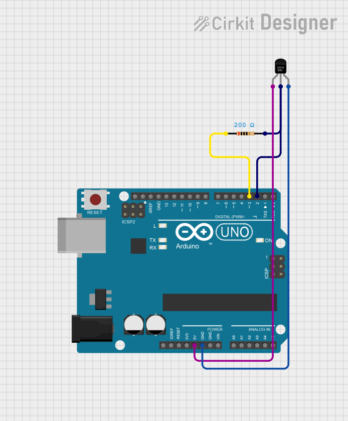
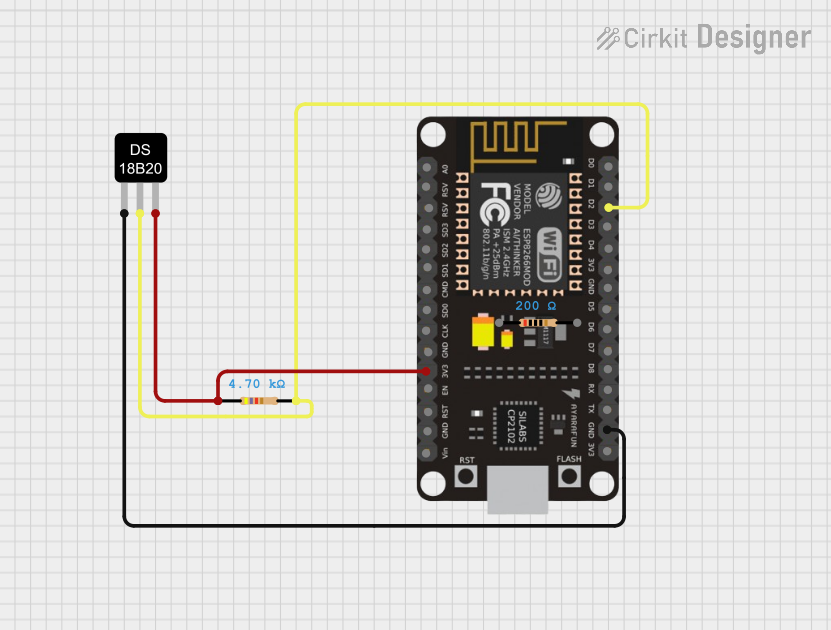
Connecting the DS18B20 to a Circuit
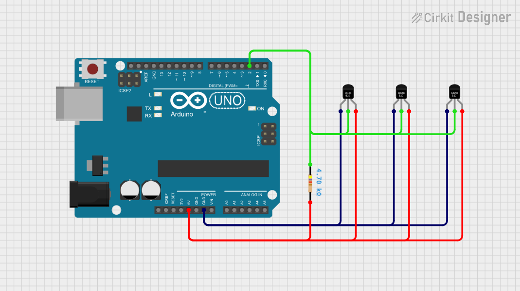
- Connect the GND pin to the ground of the power supply.
- Connect the VDD pin to a 3.0V to 5.5V power supply.
- Connect the DQ pin to a digital input/output pin on your microcontroller.
- Place a 4.7kΩ pull-up resistor between the DQ pin and the VDD pin.
Best Practices
- Use a pull-up resistor on the DQ line to ensure proper communication.
- Avoid long wire runs to minimize resistance and potential communication errors.
- Use a decoupling capacitor close to the sensor's VDD pin to stabilize the power supply.
Example Code for Arduino UNO
#include <OneWire.h>
#include <DallasTemperature.h>

// Data wire is connected to Arduino digital pin 2
#define ONE_WIRE_BUS 2

// Setup a oneWire instance to communicate with DS18B20 sensors
OneWire oneWire(ONE_WIRE_BUS);

// Pass oneWire reference to DallasTemperature library
DallasTemperature sensors(&oneWire);

void setup() {
  Serial.begin(9600);
  sensors.begin(); // Start up the library
}

void loop() {
  sensors.requestTemperatures(); // Send command to get temperatures
  float temperature = sensors.getTempCByIndex(0); // Read temperature in Celsius
  Serial.print("Temperature: ");
  Serial.print(temperature);
  Serial.println("°C");
  delay(1000); // Wait 1 second before next reading
}
Troubleshooting and FAQs
Common Issues
- No Temperature Reading: Ensure the pull-up resistor is correctly placed and the sensor is properly powered.
- Inaccurate Readings: Check for proper grounding and stable power supply. Ensure the correct resolution is set.
FAQs
Q: Can I connect multiple DS18B20 sensors to the same data line? A: Yes, the DS18B20 supports multiple devices on the same one-wire bus.
Q: How do I set the resolution of the DS18B20?
A: The resolution can be set using the DallasTemperature library functions setResolution().
Q: What is the maximum cable length for the DS18B20? A: It depends on the quality of the cable and the environment, but runs over 100 meters are possible with proper cabling and pull-up resistors.
For further assistance, consult the datasheet or contact technical support.