How to Use LoRa SOC RF ASR6601 LR01-A: Examples, Pinouts, and Specs
Introduction
The ASR6601 LR01-A is a System on Chip (SoC) designed for long-range, low-power wireless communication using LoRa technology. It integrates a high-performance RF transceiver, a microcontroller, and various peripherals into a single package. This makes it an ideal choice for Internet of Things (IoT) applications that require reliable data transmission over long distances while maintaining low power consumption.
Explore Projects Built with LoRa SOC RF ASR6601 LR01-A
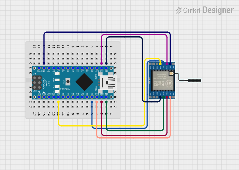


Explore Projects Built with LoRa SOC RF ASR6601 LR01-A
Common Applications and Use Cases
- Smart agriculture (e.g., soil moisture monitoring, weather stations)
- Industrial IoT (e.g., asset tracking, predictive maintenance)
- Smart cities (e.g., parking sensors, streetlight control)
- Environmental monitoring (e.g., air quality sensors, water level monitoring)
- Home automation (e.g., smart meters, security systems)
Technical Specifications
Key Technical Details
| Parameter | Value |
|---|---|
| RF Technology | LoRa |
| Frequency Range | 150 MHz to 960 MHz |
| Modulation | LoRa, (G)FSK |
| Microcontroller Core | ARM Cortex-M0+ |
| Flash Memory | 128 KB |
| RAM | 16 KB |
| Operating Voltage | 1.8 V to 3.6 V |
| Operating Temperature | -40°C to +85°C |
| Transmit Power | Up to +22 dBm |
| Sensitivity | -137 dBm (LoRa, SF12, 125 kHz bandwidth) |
| Power Consumption (Sleep) | < 2 µA |
| Package Type | QFN32 (5 mm x 5 mm) |
Pin Configuration and Descriptions
The ASR6601 LR01-A comes in a 32-pin QFN package. Below is the pin configuration:
| Pin Number | Pin Name | Description |
|---|---|---|
| 1 | VDD | Power supply input (1.8 V to 3.6 V) |
| 2 | GND | Ground |
| 3 | RF_IO | RF input/output for antenna connection |
| 4 | RESET | Reset input (active low) |
| 5 | SWDIO | Serial Wire Debug I/O |
| 6 | SWCLK | Serial Wire Debug clock |
| 7 | UART_TX | UART transmit |
| 8 | UART_RX | UART receive |
| 9 | GPIO0 | General-purpose I/O |
| 10 | GPIO1 | General-purpose I/O |
| 11 | SPI_MOSI | SPI Master Out Slave In |
| 12 | SPI_MISO | SPI Master In Slave Out |
| 13 | SPI_SCK | SPI clock |
| 14 | SPI_NSS | SPI chip select |
| 15 | I2C_SCL | I2C clock |
| 16 | I2C_SDA | I2C data |
| 17-32 | Reserved | Reserved for future use |
Usage Instructions
How to Use the Component in a Circuit
- Power Supply: Connect the VDD pin to a stable power source (1.8 V to 3.6 V) and GND to ground.
- Antenna Connection: Connect the RF_IO pin to an appropriate antenna for the desired frequency range.
- Microcontroller Interface: Use the UART, SPI, or I2C pins to communicate with an external microcontroller or other peripherals.
- Programming and Debugging: Use the SWDIO and SWCLK pins for programming and debugging the SoC.
- Reset: Connect the RESET pin to a push-button or external circuit for manual reset functionality.
Important Considerations and Best Practices
- Antenna Matching: Ensure proper impedance matching for the antenna to maximize RF performance.
- Power Decoupling: Place decoupling capacitors (e.g., 0.1 µF and 10 µF) close to the VDD pin to reduce noise.
- PCB Design: Use a ground plane and minimize trace lengths for RF signals to reduce interference.
- Firmware Development: Use the ARM Cortex-M0+ core for custom firmware development. Ensure proper initialization of the LoRa transceiver.
Example Code for Arduino UNO
Below is an example of how to interface the ASR6601 LR01-A with an Arduino UNO using UART communication:
#include <SoftwareSerial.h>

// Define RX and TX pins for SoftwareSerial
SoftwareSerial loraSerial(10, 11); // RX = pin 10, TX = pin 11

void setup() {
  // Initialize serial communication with the LoRa module
  loraSerial.begin(9600); // Set baud rate to 9600
  Serial.begin(9600);     // For debugging via Serial Monitor

  // Send initialization command to LoRa module
  loraSerial.println("AT+MODE=LoRa"); // Set mode to LoRa
  delay(100);

  // Check for response from the module
  if (loraSerial.available()) {
    String response = loraSerial.readString();
    Serial.println("LoRa Module Response: " + response);
  } else {
    Serial.println("No response from LoRa module.");
  }
}

void loop() {
  // Example: Send a test message
  loraSerial.println("Hello, LoRa!");
  delay(2000); // Wait 2 seconds before sending the next message
}
Notes:
- Replace
AT+MODE=LoRawith the appropriate AT command for your specific application. - Ensure the RX and TX pins of the ASR6601 LR01-A are connected to the correct pins on the Arduino UNO.
Troubleshooting and FAQs
Common Issues and Solutions
No Response from the Module
- Cause: Incorrect baud rate or wiring.
- Solution: Verify the baud rate and ensure proper connections for RX, TX, and GND.
Poor RF Performance
- Cause: Improper antenna design or placement.
- Solution: Use a properly matched antenna and avoid placing it near metal objects.
High Power Consumption
- Cause: Module not entering sleep mode.
- Solution: Use appropriate AT commands or firmware to enable low-power modes.
Interference with Other Devices
- Cause: Operating on a crowded frequency.
- Solution: Change the operating frequency to a less congested channel.
FAQs
Can the ASR6601 LR01-A operate on multiple frequencies?
- Yes, it supports a frequency range of 150 MHz to 960 MHz, configurable via firmware.
What is the maximum communication range?
- The range depends on environmental factors but can reach up to 15 km in open areas.
Is the module compatible with Arduino?
- Yes, it can be interfaced with Arduino using UART, SPI, or I2C communication.
How do I update the firmware?
- Use the SWDIO and SWCLK pins with a compatible programmer to update the firmware.
By following this documentation, users can effectively integrate the ASR6601 LR01-A into their IoT projects and troubleshoot common issues.