
How to Use USB-C PD Trigger Board Module: Examples, Pinouts, and Specs
 Design with USB-C PD Trigger Board Module in Cirkit Designer
Introduction
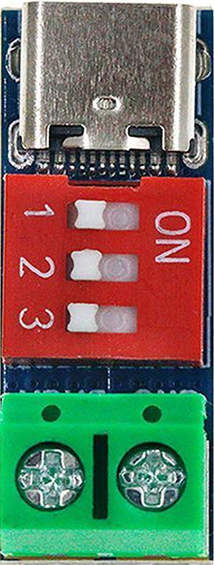
The USB-C PD Trigger Board Module (Manufacturer: Dewlawn, Part ID: USBCtester5-1118) is a versatile electronic component designed to facilitate power delivery (PD) negotiation over USB-C connections. This module enables devices to request specific voltage and current levels from a USB-C power source, making it ideal for applications requiring adjustable power management.
Common applications include:
- Prototyping and testing USB-C power delivery capabilities
- Powering devices with specific voltage and current requirements
- Battery charging circuits with adjustable power input
- USB-C power delivery education and experimentation
Explore Projects Built with USB-C PD Trigger Board Module
 Open Project in Cirkit Designer
 Open Project in Cirkit Designer
 Open Project in Cirkit Designer
 Open Project in Cirkit Designer
Explore Projects Built with USB-C PD Trigger Board Module
Open Project in Cirkit DesignerOpen Project in Cirkit DesignerOpen Project in Cirkit DesignerOpen Project in Cirkit DesignerTechnical Specifications
The following table outlines the key technical details of the USB-C PD Trigger Board Module:
| Parameter | Specification |
|---|---|
| Input Voltage | 5V to 20V (via USB-C port) |
| Output Voltage | Configurable: 5V, 9V, 12V, 15V, 20V |
| Maximum Output Current | 3A |
| Power Rating | Up to 60W |
| Communication Protocol | USB-C Power Delivery (PD) 2.0/3.0 |
| Dimensions | 25mm x 15mm x 5mm |
| Operating Temperature | -20°C to 85°C |
Pin Configuration and Descriptions
The module features the following pins for interfacing:
| Pin Name | Type | Description |
|---|---|---|
| VOUT | Output | Provides the negotiated output voltage. |
| GND | Ground | Common ground for the module and connected circuit. |
| CC1 | Input/IO | USB-C Configuration Channel 1 for PD communication. |
| CC2 | Input/IO | USB-C Configuration Channel 2 for PD communication. |
| SEL1 | Input | Voltage selection pin 1 (used in combination with SEL2 to set output voltage). |
| SEL2 | Input | Voltage selection pin 2 (used in combination with SEL1 to set output voltage). |
| EN | Input | Enable pin to activate or deactivate the module. |
Usage Instructions
How to Use the Module in a Circuit
- Connect the USB-C Power Source: Plug a USB-C power adapter into the module's USB-C port. Ensure the adapter supports the desired voltage and current levels.
- Set the Output Voltage: Use the SEL1 and SEL2 pins to configure the desired output voltage:
- SEL1 = LOW, SEL2 = LOW: 5V
- SEL1 = HIGH, SEL2 = LOW: 9V
- SEL1 = LOW, SEL2 = HIGH: 12V
- SEL1 = HIGH, SEL2 = HIGH: 20V
- Enable the Module: Pull the EN pin HIGH to activate the module and initiate power delivery negotiation.
- Connect the Load: Attach the device or circuit to the VOUT and GND pins to receive the negotiated power.
Important Considerations and Best Practices
- Ensure the USB-C power source can supply the required voltage and current for your application.
- Use appropriate heat dissipation methods if operating at high power levels (e.g., 20V @ 3A).
- Avoid shorting the VOUT and GND pins, as this may damage the module or power source.
- For safety, verify the output voltage with a multimeter before connecting sensitive devices.
Example: Using with Arduino UNO
The USB-C PD Trigger Board Module can be used to power an Arduino UNO. Below is an example of how to configure the module for 9V output and connect it to the Arduino:
Circuit Connections
- Connect the module's VOUT pin to the Arduino's VIN pin.
- Connect the module's GND pin to the Arduino's GND pin.
- Set SEL1 = HIGH and SEL2 = LOW to configure the output voltage to 9V.
- Pull the EN pin HIGH to enable the module.
Arduino Code Example
The following code demonstrates how to control the SEL1 and SEL2 pins using the Arduino:
// Define pin connections for SEL1 and SEL2
const int SEL1_PIN = 7; // Connect SEL1 to Arduino digital pin 7
const int SEL2_PIN = 8; // Connect SEL2 to Arduino digital pin 8

void setup() {
  // Set SEL1 and SEL2 as output pins
  pinMode(SEL1_PIN, OUTPUT);
  pinMode(SEL2_PIN, OUTPUT);

  // Configure the module for 9V output
  digitalWrite(SEL1_PIN, HIGH); // Set SEL1 to HIGH
  digitalWrite(SEL2_PIN, LOW);  // Set SEL2 to LOW
}

void loop() {
  // The module will maintain the configured voltage
  // No additional code is required in the loop
}
Troubleshooting and FAQs
Common Issues and Solutions
No Output Voltage
- Cause: The EN pin is not pulled HIGH.
- Solution: Ensure the EN pin is connected to a HIGH signal to enable the module.
Incorrect Output Voltage
- Cause: SEL1 and SEL2 pins are not configured correctly.
- Solution: Verify the SEL1 and SEL2 pin states match the desired voltage configuration.
Module Overheating
- Cause: Excessive current draw or insufficient heat dissipation.
- Solution: Ensure the load does not exceed the module's maximum current rating (3A). Use a heatsink if necessary.
Power Source Not Recognized
- Cause: The USB-C power adapter does not support the requested voltage/current.
- Solution: Use a USB-C power adapter that supports the desired PD profile.
FAQs
Q: Can this module be used with non-PD USB-C power sources?
A: No, the module requires a USB-C power source that supports Power Delivery (PD) for voltage negotiation.
Q: What happens if the load exceeds 3A?
A: The module may enter a protection mode or shut down to prevent damage. Always ensure the load stays within the specified limits.
Q: Can I use this module to power multiple devices simultaneously?
A: Yes, but ensure the total current draw does not exceed 3A, and the devices are compatible with the negotiated voltage.
Q: Is the module compatible with USB-C PD 3.1?
A: The module supports USB-C PD 2.0/3.0. Compatibility with PD 3.1 features is not guaranteed.